Raspberry Pi Peripherals
Run the TuyaOpen peripheral examples (examples/peripherals) on Raspberry Pi. This guide covers GPIO, I2C, SPI, PWM, UART, button input, and audio codecs: how to enable each peripheral, which TKL APIs the Linux adapter supports, and a minimal example per peripheral.
Quick start
- Make sure you have finished the basic TuyaOpen environment setup, and enter the TuyaOpen repository root directory.
- Open the configuration menu:
- Run
tos.py config menu - Select the board:
Choice a board → LINUX → Choice a board → RaspberryPi - Select the model:
Raspberry Pi Board Configuration → Choose Raspberry Pi model → Raspberry Pi 5(choose according to your actual model)
- Enable the peripherals you need: go to
Choice a board → LINUX → TKL Board Configurationand selectENABLE_GPIO/ENABLE_I2C/ENABLE_SPI/ENABLE_PWM/ENABLE_UART.
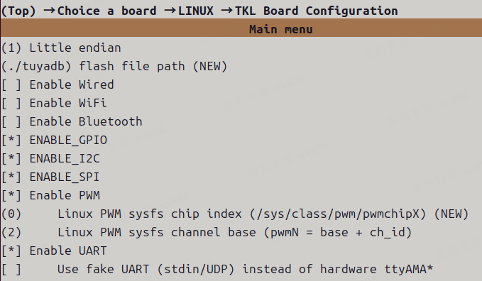
- Enter the corresponding example directory (for example
examples/peripherals/gpio), runtos.py build, then run the generated*.elfwithsudo.
Raspberry Pi supports both cross-compilation and native compilation. The build system picks a suitable mode automatically based on the current platform.
General notes
- Permissions: peripheral examples usually need to access
/dev/*or/sys/class/*. When running on Raspberry Pi, it is recommended to usesudo. - Device nodes: device node names may differ across OS images (for example, UART can be
/dev/ttyAMA0or/dev/ttyS0). If the node names do not match TuyaOpen port mapping, adapt to the actual nodes or adjust configuration. OPRT_NOT_SUPPORTED: some TKL peripheral APIs are kept for a unified abstraction across MCU/Linux. On Raspberry Pi (Linux userspace), if the underlying standard interfaces (such as i2c-dev/spidev/sysfs/tty/gpio-cdev) cannot provide the capability, or extra kernel drivers/subsystems are required but not implemented in the current adapter, the API will returnOPRT_NOT_SUPPORTED.
GPIO example
This section shows how to use TuyaOpen to operate GPIO on Raspberry Pi.
Adapter notes (Linux TKL GPIO)
Supported (available)
- Basic read/write
tkl_gpio_init()/tkl_gpio_deinit(): request/release a line handle based on Linux gpio-cdev (/dev/gpiochip*).tkl_gpio_write()/tkl_gpio_read(): write/read levels viaGPIOHANDLE_*ioctl.
- Interrupt callback (event notification)
tkl_gpio_irq_init()/tkl_gpio_irq_enable()/tkl_gpio_irq_disable(): request an event fd viaGPIO_GET_LINEEVENT_IOCTL, and use a thread topoll()and trigger callbacks.
Notes / limitations
- Requires
/dev/gpiochip*to be available (kernel must enable the GPIO character device interface, and the current user must have permission; typically run the examples withsudo). - On Linux,
TUYA_GPIO_NUM_Eis interpreted as the gpiochip line offset. On Raspberry Pi it usually matches BCM GPIO numbers, but this may vary by distro/kernel configuration. Verify withgpioinfo/pinctrl. TUYA_GPIO_IRQ_LOW/HIGHis an "approximation": the adapter listens for edge events and then reads the current level for filtering; it is not a true level-triggered hardware interrupt.
Reference
- For GPIO API definitions, parameter descriptions, and adaptation notes, see GPIO Driver.
Enter the example directory
cd examples/peripherals/gpio
Configuration
Start the configuration menu:
tos.py config menu
After selecting board and model as described in "Quick start", go to Choice a board → LINUX → TKL Board Configuration and select ENABLE_GPIO.
For the GPIO pinout and the RP1 mux/function table, see the Raspberry Pi 5 GPIO Reference.
In Application config, choose appropriate pins for:
- output pin
- input pin
- irq pin
Make sure the selected pins are free and match your wiring.
Build and run
Build:
tos.py build
After building, an executable like gpio_1.0.0.elf will be generated. Run it on Raspberry Pi:
sudo ./gpio_1.0.0.elf
Minimal example
The code below demonstrates:
- Initializing an output pin and toggling it once per second
- Initializing an input pin and reading its level
This snippet shows only the core calls. For a complete buildable project, see examples/peripherals/gpio.
#include "tal_api.h"
#include "tkl_gpio.h"

// These macros are usually configured via Kconfig/Application config in the example project
// #define EXAMPLE_OUTPUT_PIN ...
// #define EXAMPLE_INPUT_PIN  ...

static void gpio_min_demo(void)
{
  TUYA_GPIO_BASE_CFG_T out_cfg = {
    .mode   = TUYA_GPIO_PUSH_PULL,
    .direct = TUYA_GPIO_OUTPUT,
    .level  = TUYA_GPIO_LEVEL_LOW,
  };
  TUYA_GPIO_BASE_CFG_T in_cfg = {
    .mode   = TUYA_GPIO_PULLUP,
    .direct = TUYA_GPIO_INPUT,
  };

  tkl_gpio_init(EXAMPLE_OUTPUT_PIN, &out_cfg);
  tkl_gpio_init(EXAMPLE_INPUT_PIN,  &in_cfg);

  while (1) {
    static uint8_t level = 0;
    TUYA_GPIO_LEVEL_E in_level = TUYA_GPIO_LEVEL_LOW;

    level ^= 1;
    tkl_gpio_write(EXAMPLE_OUTPUT_PIN, level ? TUYA_GPIO_LEVEL_HIGH : TUYA_GPIO_LEVEL_LOW);

    tkl_gpio_read(EXAMPLE_INPUT_PIN, &in_level);
    PR_NOTICE("GPIO in=%d out=%d", (int)in_level, (int)level);

    tal_system_sleep(1000);
  }
}
I2C example
This section shows how to use TuyaOpen to operate I2C on Raspberry Pi.
Adapter notes (Linux TKL I2C)
Supported (available)
- Basic master send/receive
tkl_i2c_master_send(): write to a given device address (uses/dev/i2c-X+I2C_SLAVE+write()).tkl_i2c_master_receive(): read from a given device address (usesI2C_SLAVE+read()).
- Common "register read" combined transaction (Repeated Start)
- When
tkl_i2c_master_send(..., xfer_pending=true)is immediately followed bytkl_i2c_master_receive(), they are merged into a singleI2C_RDWRtransaction, implementing "write register address/command, then repeated-start read data".
- When
- Address probe (scan)
- When
tkl_i2c_master_send()is called withsize==0, the adapter uses SMBus "quick" to probe whether the device ACKs (useful for simple address scans).
- When
Not supported yet (API kept; current implementation returns OPRT_NOT_SUPPORTED)
- Slave mode:
tkl_i2c_set_slave_addr(),tkl_i2c_slave_send(),tkl_i2c_slave_receive(). - Interrupt/event callback:
tkl_i2c_irq_init(),tkl_i2c_irq_enable(),tkl_i2c_irq_disable(). - Extended control/status query:
tkl_i2c_ioctl(),tkl_i2c_get_status().- Note:
tkl_i2c_get_status()currently zeros the output structure and returnsOPRT_NOT_SUPPORTED. Do not rely on its output.
- Note:
Reference
- For I2C API definitions, parameter descriptions, and adaptation notes, see I2C Driver.
Enable I2C on Raspberry Pi (system configuration)
In a Raspberry Pi terminal, run:
sudo raspi-config
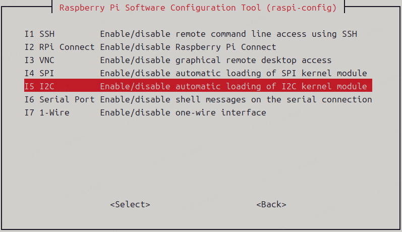
In raspi-config, enable I2C via:
3 Interface Options→I5 I2C→Enable
Verify the device node is created:
ls /dev | grep i2c
Example 1: scan the bus (i2c_scan)
Enter the example directory:
cd examples/peripherals/i2c/i2c_scan
Configure:
tos.py config menu
Choice a board → LINUX → TKL Board Configuration: selectENABLE_I2CApplication config: configurei2c port,sda pin,scl pin
Notes:
- The Linux adapter will access
/dev/i2c-${port}. - On Raspberry Pi, it is commonly
/dev/i2c-1(GPIO2/3), soi2c portshould usually match the actual device node number.
Build and run:
tos.py build
sudo ./i2c_scan_1.0.0.elf
If a device is found, you will see logs like:
[example_i2c_scan.c:xx] i2c device found at address: 0x44
Minimal example
The code below demonstrates scanning I2C 7-bit addresses (on Linux, size==0 triggers the quick probe path):
For a complete buildable project, see examples/peripherals/i2c/i2c_scan.
#include "tal_api.h"
#include "tkl_i2c.h"

static void i2c_scan_demo(TUYA_I2C_NUM_E port)
{
  for (uint8_t addr = 0x08; addr <= 0x77; addr++) {
    // size=0: probe
    if (tkl_i2c_master_send(port, addr, NULL, 0, TRUE) == OPRT_OK) {
      PR_NOTICE("I2C device found: 0x%02X", addr);
    }
  }
}
Example 2: read temperature/humidity (sht3x_4x_sensor)
Enter the example directory:
cd examples/peripherals/i2c/sht3x_4x_sensor
Configure and build the same way as above. In Application config, choose:
sensor type: sht3x or sht4x
Run:
sudo ./sht3x_4x_sensor_1.0.0.elf
You should see temperature and humidity logs printed periodically.
SPI example
This section shows how to use TuyaOpen to operate SPI (userspace spidev) on Raspberry Pi.
Adapter notes (Linux TKL SPI)
Supported (available)
- Master mode
tkl_spi_init(): open/dev/spidevX.Yand configure mode/bits/speed/bitorder.- Only
TUYA_SPI_ROLE_MASTER/TUYA_SPI_ROLE_MASTER_SIMPLEXare supported.
- Basic send/receive
tkl_spi_send(): useswrite().tkl_spi_recv(): usesread().
- Transfers
tkl_spi_transfer(): full-duplex TX/RX viaSPI_IOC_MESSAGE(1).tkl_spi_transfer_with_length(): "send then receive" viaSPI_IOC_MESSAGE(2).
- Counters/status (compatibility APIs)
tkl_spi_get_data_count(): returns the byte count of the most recent transfer.tkl_spi_get_status(): returnsOPRT_OKand currently only zeros the struct (no real status).
Not supported yet (API kept; current implementation returns OPRT_NOT_SUPPORTED)
- Interrupt callback:
tkl_spi_irq_init()/tkl_spi_irq_enable()/tkl_spi_irq_disable(). - Extended control:
tkl_spi_ioctl().
Behavior limits / compatibility implementations
- Abort transfer:
tkl_spi_abort_transfer()returnsOPRT_OKbut does not perform a real abort. - DMA length:
tkl_spi_get_max_dma_data_length()returns 0 (not meaningful for Linux spidev).
Port to device-node mapping (default)
| spi port | device node |
|---|---|
| 0 | /dev/spidev0.0 |
| 1 | /dev/spidev0.1 |
| 2 | /dev/spidev1.0 |
| 3 | /dev/spidev1.1 |
| 4 | /dev/spidev2.0 |
| 5 | /dev/spidev2.1 |
Reference
- For SPI API definitions, parameter descriptions, and adaptation notes, see SPI Driver.
Enable SPI on Raspberry Pi (system configuration)
sudo raspi-config
In raspi-config, enable SPI via:
3 Interface Options→I4 SPI→Enable
Verify the device node is created:
ls /dev | grep spidev
In TuyaOpen SPI examples, Application config -> spi port is a port number. The Linux adapter maps the port number to a device node (see prv_spi_dev_path() in platform/LINUX/tuyaos_adapter/src/tkl_spi.c):
spi port = 0→/dev/spidev0.0spi port = 1→/dev/spidev0.1spi port = 2→/dev/spidev1.0spi port = 3→/dev/spidev1.1spi port = 4→/dev/spidev2.0spi port = 5→/dev/spidev2.1
For example, for spidev0.0 / spidev0.1, set spi port to 0 / 1.
Enter the example directory
cd examples/peripherals/spi
Configure, build, and run
Configure:
tos.py config menu
Choice a board → LINUX → TKL Board Configuration: selectENABLE_SPIApplication config: configurespi port,spi baudrate
Recommended spi port:
- To use
/dev/spidev0.0: set to0 - To use
/dev/spidev0.1: set to1
For spi baudrate (Hz), it is recommended to start with 1000000 or 8000000 to validate loopback/communication, then increase gradually based on your peripheral's capability.
Build and run:
tos.py build
sudo ./spi_1.0.0.elf
Minimal example
The code below demonstrates SPI master sending a fixed string (on Linux it goes through /dev/spidevX.Y):
For a complete buildable project, see examples/peripherals/spi.
#include "tal_api.h"
#include "tkl_spi.h"

// #define EXAMPLE_SPI_PORT ...
// #define EXAMPLE_SPI_BAUDRATE ...

static void spi_min_demo(void)
{
  TUYA_SPI_BASE_CFG_T cfg = {
    .mode     = TUYA_SPI_MODE0,
    .freq_hz  = EXAMPLE_SPI_BAUDRATE,
    .databits = TUYA_SPI_DATA_BIT8,
    .bitorder = TUYA_SPI_ORDER_LSB2MSB,
    .role     = TUYA_SPI_ROLE_MASTER,
    .type     = TUYA_SPI_AUTO_TYPE,
  };

  uint8_t tx[] = "Hello Tuya";
  tkl_spi_init(EXAMPLE_SPI_PORT, &cfg);

  while (1) {
    tkl_spi_send(EXAMPLE_SPI_PORT, tx, sizeof(tx));
    tal_system_sleep(500);
  }
}
PWM example
This section shows how to use TuyaOpen to operate PWM on Raspberry Pi.
Adapter notes (Linux TKL PWM)
Supported (available)
- PWM output (
/sys/class/pwm)tkl_pwm_init(): export the channel and configure polarity/period/duty.tkl_pwm_start()/tkl_pwm_stop(): start/stop via writingenable.tkl_pwm_duty_set(): update duty cycle.tkl_pwm_frequency_set(): update frequency.tkl_pwm_polarity_set(): update polarity.tkl_pwm_info_set()/tkl_pwm_info_get(): set/get a full parameter set (get returns the software-saved cfg).tkl_pwm_multichannel_start()/tkl_pwm_multichannel_stop(): start/stop multiple channels sequentially.tkl_pwm_deinit(): stop and unexport.
Not supported yet (API kept; current implementation returns OPRT_NOT_SUPPORTED)
- PWM capture:
tkl_pwm_cap_start()/tkl_pwm_cap_stop().- Note: the current implementation returns
OPRT_NOT_SUPPORTEDdirectly.
- Note: the current implementation returns
Reference
- For PWM API definitions, parameter descriptions, and adaptation notes, see PWM Driver.
PWM experiment steps (example: output PWM square wave on GPIO18)
Enter the example directory
cd examples/peripherals/pwm
Enable PWM on Raspberry Pi (system configuration)
-
Make sure the pin is not occupied:
pinctrl get 18If it is not multiplexed, you will usually see something like:
18: no pd | -- // GPIO18 = none
-
Enable the PWM overlay:
Append to the end of
/boot/firmware/config.txt:dtoverlay=pwm,pin=18,func=2Reboot Raspberry Pi to apply.
-
After reboot, verify the mapping:
pinctrl get 18You should see something like (meaning the pin is switched to a PWM channel):
18: a3 pd | lo // GPIO18 = PWM0_CHAN2
Configuration
Start the configuration menu:
tos.py config menu
Choice a board → LINUX → TKL Board Configuration: selectENABLE_PWM- In the same configuration tree, set:
PWM_SYSFS_CHIP = 0(maps to/sys/class/pwm/pwmchip0)PWM_SYSFS_CHANNEL_BASE = 2(because GPIO18 maps toPWM0_CHAN2)
Application config: choosepwm port = 0(because it isPWM0)
Build and run
tos.py build
sudo ./pwm_1.0.0.elf
Minimal example
The code below demonstrates PWM output (init + start):
For a complete buildable project, see examples/peripherals/pwm.
#include "tal_api.h"
#include "tkl_pwm.h"

// #define EXAMPLE_PWM_PORT ...
// #define EXAMPLE_PWM_FREQUENCY ...
// #define EXAMPLE_PWM_DUTY ... // 1-10000

static void pwm_min_demo(void)
{
  TUYA_PWM_BASE_CFG_T cfg = {
    .duty      = EXAMPLE_PWM_DUTY,
    .frequency = EXAMPLE_PWM_FREQUENCY,
    .polarity  = TUYA_PWM_NEGATIVE,
  };

  tkl_pwm_init(EXAMPLE_PWM_PORT, &cfg);
  tkl_pwm_start(EXAMPLE_PWM_PORT);

  while (1) {
    tal_system_sleep(2000);
  }
}
To quickly verify the sysfs nodes match expectations, check whether the corresponding pwm2 exists (or can be exported) under /sys/class/pwm/pwmchip0/.
PWM sysfs depends on kernel and overlay configuration. The path /boot/firmware/config.txt may differ by OS image; use the actual path on your system.
UART example
This section shows how to use TuyaOpen to operate UART on Raspberry Pi.
Adapter notes (Linux TKL UART)
Supported (available)
- Basic send/receive
tkl_uart_init(): open the UART device and configure baud/data bits/parity/stop bits via termios.tkl_uart_write(): useswrite().tkl_uart_read(): usesread().tkl_uart_deinit(): close fd and stop the RX thread.
- RX callback notification (approx. "interrupt" semantics)
tkl_uart_rx_irq_cb_reg(): register the RX callback.- On Linux, a thread
select()s for fd readability and triggers the callback.
Not supported yet (API kept; current implementation returns OPRT_NOT_SUPPORTED)
tkl_uart_set_tx_int()/tkl_uart_set_rx_flowctrl()/tkl_uart_wait_for_data()/tkl_uart_ioctl().
Empty implementation (no effect)
tkl_uart_tx_irq_cb_reg(): currently a no-op.
Device node mapping (related to the FAKE UART switch)
- When
TKL_UART_REDIRECT_LOG_TO_STDOUT = n(UART redirection disabled; use real hardware UART), the default mapping is:port 0 -> /dev/ttyAMA0port 1 -> /dev/ttyAMA1port 2 -> /dev/ttyAMA2
- When
TKL_UART_REDIRECT_LOG_TO_STDOUT = y(UART redirection enabled), the adapter does not access/dev/ttyAMA*and uses a Dummy UART implementation (see below).
Reference
- For UART API definitions, parameter descriptions, and adaptation notes, see UART Driver.
Hardware wiring notes (physical UART)
If you use a physical UART (for example, Raspberry Pi UART pins connected to a USB-TTL module or another board's UART):
- Make sure both sides share a common ground (GND). Without common ground, typical symptoms include garbled RX data, missing bytes, or very unstable communication.
UART redirection (Dummy UART: stdin/stdout/UDP)
To make UART-related components runnable even without real UART hardware connected, Linux provides a switch TKL_UART_REDIRECT_LOG_TO_STDOUT (in LINUX → TKL Board Configuration).
When redirection (Dummy UART) is enabled, the behavior in tkl_uart.c is roughly as follows (different from real UART; mainly for debugging/demo):
TUYA_UART_NUM_0(port 0):- RX: read from the current process standard input
/dev/stdin(your terminal keyboard input when running*.elf). - TX: write to
stdout(printed directly in the terminal). - Typical use: in SSH/local terminals, use "keyboard input → UART RX", and see "UART TX" output on-screen, without relying on
/dev/ttyAMA*.
- RX: read from the current process standard input
TUYA_UART_NUM_1(port 1):- RX: receive via UDP socket and feed bytes to the upper-layer RX callback.
- TX: send data to the peer via UDP socket.
- Note: in the current implementation, the bind/send IP and ports are fixed (environment dependent). In many networks you need to modify the adapter source code and rebuild.
Limitations/notes of Dummy mode:
- Baud rate/parity/stop bits etc. are not equivalent to real UART in Dummy mode (for port 0, stdin is only switched to non-canonical mode for immediate reads; stdout has no real serial timing).
- Dummy mode is mainly for "making the feature run / interactive demo", and is not suitable for serious UART protocol timing verification.
How to choose whether to use UART redirection:
- If you want the UART example/CLI to use Raspberry Pi physical UART pins (
/dev/ttyAMA*or/dev/ttyS*), go to:Choice a board → LINUX → TKL Board Configuration- set
UART redirection (stdin/stdout/UDP) instead of hardware ttyAMA*ton - Note: when this option is not selected, it uses physical UART and accesses real
ttyAMA*/ttyS*device nodes.
- If you just want to quickly validate UART logic and you do not have USB-TTL/hardware loopback yet, keep it as
y.
Note: QR-code output channel in your_chat_bot provisioning (UART redirection)
When running your_chat_bot on Linux/Raspberry Pi for provisioning demo, it is recommended to enable TKL_UART_REDIRECT_LOG_TO_STDOUT so that the QR-code content is printed directly in the current terminal.
1) Expected behavior (with redirection enabled)
- The QR code (string/ASCII art) is visible directly in the terminal where you run
your_chat_bot*.elf.
2) How it works (output via UART0 TX)
- During provisioning,
your_chat_bottypically sends the QR-code content through UART0 (TUYA_UART_NUM_0). - When
TKL_UART_REDIRECT_LOG_TO_STDOUT = y: UART0 TX is mapped tostdout, so the QR code shows in the terminal. - When
TKL_UART_REDIRECT_LOG_TO_STDOUT = n: UART0 TX writes to the real UART device (for example/dev/ttyAMA0//dev/ttyS0), so it will not show in the terminal; it is output on the serial line.
Enable UART on Raspberry Pi (system configuration)
sudo raspi-config
In raspi-config, configure serial port via:
3 Interface Options→I6 Serial Port
It is usually recommended to choose:
- Disable serial login shell
- Enable serial port hardware
Check the UART device nodes:
ls -l /dev/ttyAMA* /dev/ttyS* 2>/dev/null
Enter the example directory
cd examples/peripherals/uart
Configure, build, and run
Configure:
tos.py config menu
Choice a board → LINUX → TKL Board Configuration: selectENABLE_UART
Optional: in the same menu, set UART redirection (stdin/stdout/UDP) instead of hardware ttyAMA* as needed (whether to enable UART redirection / Dummy UART).
- Selected (
*): enable UART redirection (Dummy UART: stdin/stdout/UDP); no dependency on real UART device nodes. - Not selected (
ttyAMA*/ttyS*device nodes).
Build:
tos.py build
Run:
sudo ./uart_1.0.0.elf
The example uses TUYA_UART_NUM_0 (UART0) by default. On Raspberry Pi, UART0 may be occupied by the system console. If you see no echo or open failures, check serial-port usage and adjust the UART port used by the example or the adapter device-node mapping.
Minimal example 1: interactive echo
This example is best for quickly validating the UART path in Dummy UART redirection (stdin/stdout) mode: whatever you type in the terminal is echoed back.
This approach is consistent with examples/peripherals/uart.
#include "tal_api.h"

#include "tkl_output.h"

#define UART_NUM TUYA_UART_NUM_0

static void uart_echo_demo(void)
{
  TAL_UART_CFG_T cfg = {0};
  cfg.base_cfg.baudrate = 115200;
  cfg.base_cfg.databits = TUYA_UART_DATA_LEN_8BIT;
  cfg.base_cfg.stopbits = TUYA_UART_STOP_LEN_1BIT;
  cfg.base_cfg.parity   = TUYA_UART_PARITY_TYPE_NONE;
  cfg.rx_buffer_size    = 256;
  cfg.open_mode         = O_BLOCK;

  tal_uart_init(UART_NUM, &cfg);
  tal_uart_write(UART_NUM, (const uint8_t*)"Please input text:\r\n", sizeof("Please input text:\r\n") - 1);

  while (1) {
    uint8_t buf[128];
    int n = tal_uart_read(UART_NUM, buf, sizeof(buf));
    if (n > 0) {
      tal_uart_write(UART_NUM, buf, n);
    } else {
      tal_system_sleep(10);
    }
  }
}
Minimal example 2: hardware loopback self-test (short TX and RX)
This example performs a self-test of "whether transmitted data can be read back unchanged" (validated by memcmp). It usually requires:
- Disable Dummy redirection (use physical UART device nodes)
- Short TX and RX on the same UART (and ensure common GND)
#include <string.h>

#include "tal_api.h"
#include "tkl_uart.h"

static OPERATE_RET uart_loopback_test(TUYA_UART_NUM_E port)
{
  TUYA_UART_BASE_CFG_T cfg = {0};
  cfg.baudrate = 115200;
  cfg.databits = TUYA_UART_DATA_LEN_8BIT;
  cfg.parity   = TUYA_UART_PARITY_TYPE_NONE;
  cfg.stopbits = TUYA_UART_STOP_LEN_1BIT;
  cfg.flowctrl = TUYA_UART_FLOWCTRL_NONE;

  OPERATE_RET ret = tkl_uart_init(port, &cfg);
  if (ret != OPRT_OK) {
    return ret;
  }

  const uint32_t timeout_ms = 5000;
  const int bufsize = 8;
  uint8_t tx[bufsize];
  uint8_t rx[bufsize];

  for (int i = 0; i < bufsize; i++) {
    tx[i] = (uint8_t)('A' + i);
  }

  for (int round = 0; round < 3; round++) {
    memset(rx, 0, sizeof(rx));

    int wr = tkl_uart_write(port, tx, sizeof(tx));
    if (wr != (int)sizeof(tx)) {
      ret = OPRT_COM_ERROR;
      break;
    }

    int got = 0;
    SYS_TIME_T start = tal_system_get_millisecond();
    while (got < (int)sizeof(rx)) {
      SYS_TIME_T now = tal_system_get_millisecond();
      if ((uint32_t)(now - start) > timeout_ms) {
        ret = OPRT_TIMEOUT;
        break;
      }

      int rd = tkl_uart_read(port, rx + got, (uint32_t)sizeof(rx) - (uint32_t)got);
      if (rd > 0) {
        got += rd;
      } else {
        tal_system_sleep(5);
      }
    }

    if (ret != OPRT_OK) {
      break;
    }
    if (memcmp(tx, rx, sizeof(tx)) != 0) {
      ret = OPRT_COM_ERROR;
      break;
    }
  }

  tkl_uart_deinit(port);
  return ret;
}
Button example
This example demonstrates how to handle button input on Raspberry Pi using TuyaOpen's Button component (TDL Button management layer).
Adapter notes (Raspberry Pi keyboard-simulated button)
On Raspberry Pi, buttons are simulated via keyboard input by default: pressing a character in the terminal where you run *.elf triggers a button event.
- Enabled by board Kconfig:
ENABLE_KEYBOARD_INPUT - Trigger character is specified by
BUTTON_NAME(defaults)
In the example project, the log for TDL_BUTTON_PRESS_DOWN is printed as single click (see examples/peripherals/button/src/example_button.c). It represents the press-down event.
Enter the example directory
cd examples/peripherals/button
Configuration
tos.py config choice
Select the number corresponding to RaspberryPi.config and press Enter.
tos.py config menu
After completing board/model selection per "Quick Start", go to:
Choice a board → LINUX → Raspberry Pi Board Configuration- Confirm
Enable keyboard input for Raspberry Piis checked. - Set
Keyboard button device value, for example:s
- Confirm
Note: Keyboard button device value corresponds to the board config item BUTTON_NAME, meaning "which keyboard character is used to simulate the button".
- Set to
s: pressingsin the terminal running*.elftriggers a button event nameds. - It is recommended to use a single character (e.g.,
s/a/d/1). Avoid multi-character strings to prevent confusion if some implementations only take the first character.
Build and run
Build:
tos.py build
Run:
sudo ./button_1.0.0.elf
Expected behavior
- Press the character corresponding to
BUTTON_NAME(defaults) in the terminal, and it printss: single clickonce (press-down event). - Hold it for about 3 seconds (in the example,
long_start_valid_time=3000ms), and it printss: long press(long-press event).
Audio codecs example (audio_codecs)
This example demonstrates recording + playback via ALSA on Raspberry Pi (PCM 16k/16bit/mono), and shows how to use TuyaOpen's TDL Audio management-layer APIs.
Adapter notes (Linux ALSA)
- On Raspberry Pi (Linux), audio is accessed via ALSA
/dev/snd/*. - This example depends on the
src/peripherals/audio_codecscomponent and uses the ALSA driver implementation (tdd_audio_alsa.c). - It is recommended to run with
sudo, or ensure the current user is in theaudiogroup (otherwise opening sound card device nodes may fail).
Pre-check (verify the USB sound card is recognized)
Using a USB audio module (e.g., YD1076/Y1076) as an example, run on Raspberry Pi:
aplay -l
arecord -l
ls -la /dev/snd/
You should see a device like card 2: Y1076 ... in the list.
Enter the example directory
cd examples/peripherals/audio_codecs
Configuration
Open the configuration UI:
tos.py config choice
Select the number corresponding to RaspberryPi.config and press Enter.
tos.py config menu
After completing board selection per "Quick Start", go to:
Choice a board → LINUX → Choice a board → RaspberryPi → Raspberry Pi Board Configuration- Confirm
Enable keyboard input for Raspberry Piis checked. - Set
Keyboard button device value, for example:s
- Confirm
Build and run
Build:
tos.py build
Run (recommended with sudo on Raspberry Pi):
sudo ./audio_codecs_1.0.0.elf
Interaction: the example uses keyboard input to simulate a button by default (usually s). Press and hold to start recording, release to stop recording and play back (follow actual logs/behavior).
Common troubleshooting
- Failed to open
defaultdevice
If you see errors like:
ALSA lib pcm_asym.c:... capture slave is not definedAudio capture device 'default' not available: Invalid argument
It indicates that the ALSA default PCM config on the current system cannot be used for recording.
Possible solution:
- Create
/etc/asound.confon Raspberry Pi and mapdefaultto the USB sound card:
sudo tee /etc/asound.conf >/dev/null <<'EOF'
pcm.!default {
    type asym
    playback.pcm "plughw:CARD=Y1076,DEV=0"
    capture.pcm  "plughw:CARD=Y1076,DEV=0"
}

ctl.!default {
    type hw
    card "Y1076"
}
EOF
After creating it, you can validate with:
arecord -D default -f S16_LE -c1 -r16000 -d2 /tmp/t.wav
aplay -D default /tmp/t.wav