BRD2605A Dev Kit
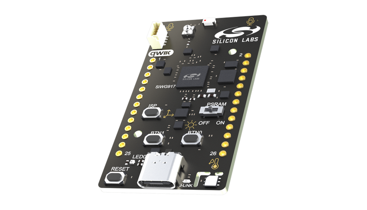
The BRD2605A dev kit is Silicon Labs' official SiWx917 Wi-Fi 6 & Bluetooth LE Dev Kit (SiWx917-DK2605A), with TuyaOpen board support. On-board SEGGER J-Link debugger.
Software build configuration
The board configuration file defines the configuration parameters for peripheral drivers, pin mapping, the BSP package, and third-party libraries. Building with the kit's preconfigured board file saves most of the hardware adaptation effort.
:::tip Want to develop new peripherals? Config notes:
- To add peripherals, write the drivers at the application layer. BSP drivers mainly serve the peripherals fixed on the board.
- Peripheral needs differ between applications; adjust the Config file accordingly.
- Different applications may need different third-party library parameters.
- Recommended: treat the initial configuration file as the board base template and extend it for your own development. :::
Hardware overview
The kit shares its toolchain with Silicon Labs' official flow: the SDK board definition comes from the brd2605a configuration shipped inside the WiseConnect SDK, and the on-board debugger exposes both J-Link SWD and a virtual COM port (VCOM). The board also carries temperature/humidity, ambient-light, and 6-axis sensors plus a Qwiic connector.
Kit highlights
- SiWG917M111MGTBA module
- ARM Cortex-M4 @ 180 MHz
- 8 MB flash + 320 kB on-chip RAM
- On-board SEGGER J-Link and virtual COM port (VCOM), one USB Type-C cable for flashing and logs
- Temperature/humidity, ambient-light, and 6-axis inertial sensors
- MEMS stereo microphone
- RGB LED and two buttons (BTN0/BTN1)
- Two-row EXP1A/EXP1B expansion header, Qwiic connector
Detailed specifications
| Feature | Specification |
|---|---|
| On-board module | SiWG917M111MGTBA |
| CPU | ARM Cortex-M4 @ 180 MHz |
| Wireless | Wi-Fi 6 (802.11ax, 2.4 GHz) + Bluetooth LE, 2.4 GHz ceramic chip antenna |
| Flash / RAM | 8 MB flash, 320 kB on-chip RAM |
| Sensors | Temperature/humidity, ambient light, 6-axis inertial |
| Audio | MEMS stereo microphone |
| Interaction | RGB LED, two buttons (BTN0/BTN1) |
| Expansion | 26-pin 2.54 mm dual-row header (EXP1A/EXP1B), Qwiic connector |
| Debug | On-board SEGGER J-Link + virtual COM port (VCOM), USB powered |
Pin definitions
Breakout headers
Expansion signals are brought to a 26-pin 2.54 mm dual-row header, with the odd row silkscreened EXP1A and the even row EXP1B.
EXP1A
| Pin | Signal | Pin | Signal |
|---|---|---|---|
| 1 | VMCU | 15 | SENSOR_I2C (SCL) |
| 3 | SDIO CLK | 17 | BOARD_ID_I2C |
| 5 | SDIO CMD | 19 | BOARD_ID_I2C |
| 7 | SDIO D0 | 21 | GPIO_6 |
| 9 | SDIO D1 | 23 | GPIO_10 |
| 11 | SDIO D2 | 25 | GPIO_12 |
| 13 | SDIO D3 |
EXP1B
| Pin | Signal | Pin | Signal |
|---|---|---|---|
| 2 | VMCU | 16 | SENSOR_I2C (SDA) |
| 4 | IMU SPI CLK | 18 | NC |
| 6 | IMU SPI CS | 20 | NC |
| 8 | IMU SPI MOSI | 22 | GPIO_11 |
| 10 | IMU SPI MISO | 24 | GPIO_7 |
| 12 | VCOM TX | 26 | GND |
| 14 | VCOM RX |
Notes:
- SENSOR_I2C is the bus of the on-board sensors; BOARD_ID_I2C is the board-identification I2C (routed through 4.7 kΩ resistors). Both can serve as general-purpose I2C when you expand the board.
- The six SDIO lines and four IMU SPI lines expose chip interfaces on the header; if you don't attach an SDIO device, those 10 pins work as GPIOs.
- VCOM wires the debugger's virtual UART straight to the header; mind the overlap with the USB virtual COM when attaching serial devices.
Debugging does not consume the expansion header: the on-board J-Link (SWD) and VCOM work directly over USB Type-C with no wiring. For background, see the UG581 user guide.
Board-level pins
| Function | Kconfig | TUYA GPIO | Chip pad | Registered name |
|---|---|---|---|---|
| Button 1 | BOARD_SW1_PIN | 49 | HP 49 | SW1 |
| Button 2 | BOARD_SW2_PIN | 2 | UULP 2 | SW2 |
| Button 3 | BOARD_SW3_PIN | 3 | UULP 3 | SW3 |
| LED R | BOARD_LEDR_PIN | 50 | HP 50 | LEDR |
| LED G | BOARD_LEDG_PIN | 51 | HP 51 | LEDG |
| LED B | BOARD_LEDB_PIN | 15 | HP 15 | LEDB |
Downloads
BRD2605A board
- BRD2605A-A02 schematic (PDF): complete circuit diagram of the board.
- UG581 BRD2605A user guide (PDF): board features, peripherals, and the expansion header.
- Product page (Silicon Labs): official resources and documentation.
- Purchase (Digi-Key): purchase channel.
SiWx917 chip documentation (Silicon Labs)
- SiWx917 documentation: official entry point for chip, SDK, and tooling docs.
- WiSeConnect SDK repository (GitHub): host drivers and TA firmware notes.
Related docs / demos
- SiWx917 Quick Start: environment setup, flashing, and provisioning.
- your_chat_bot demo
- SiWx917 Overview
- SiWx917 AI Dev Kit