
SiWx917 AI Dev Kit

The SiWx917 AI dev kit (SIWX917_AI_DEV_KIT, SEKORM part SK_SIWG917_AI_MB) is a voice-and-display interaction board built around the SiWG917M111 module.

SK_SIWG917_AI_MB AI dev kit

Software build configurationโ€‹

The board configuration file defines the configuration parameters for peripheral drivers, pin mapping, the BSP package, and third-party libraries. Building with the kit's preconfigured board file saves most of the hardware adaptation effort.

:::tip Want to develop new peripherals? Config notes:

  • To add peripherals, write the drivers at the application layer. BSP drivers mainly serve the peripherals fixed on the board.
  • Peripheral needs differ between applications; adjust the Config file accordingly.
  • Different applications may need different third-party library parameters.
  • Recommended: treat the initial configuration file as the board base template and extend it for your own development. :::

To enable a Config, see CLI - tos.py tools - config choice.

Build flagSIWX917.configSiWx917 AI dev kit board config - config file
App configSIWX917_AI_DEV_KIT.configyour_chat_bot example config - config file
BSP sourcesSiWx917 AI dev kit BSP sources

Hardware overviewโ€‹

The kit is designed around voice and display interaction: the SiWG917M111 module provides the dual-core Wi-Fi 6 + BLE radio and 8 MB of in-package PSRAM; application code runs on the Cortex-M4, and audio uses the on-chip I2S interface with no external codec. Flashing works through an external J-Link (SWD) or the ISP UART, and logs leave on the ULP UART.
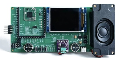
Kit highlightsโ€‹

  • SiWG917M111 module (Wi-Fi 6 2.4 GHz + Bluetooth LE)
  • ARM Cortex-M4 @ 180 MHz
  • 8 MB flash + 8 MB in-package PSRAM
  • ST7789 320ร—240 SPI display (RGB565)
  • Analog microphone + speaker (on-chip I2S, no external codec)
  • Chat button SW1 and buttons SW2/SW3
  • RGB LED
  • J-Link (SWD) or ISP UART flashing; ULP UART logs

Detailed specificationsโ€‹

FeatureSpecification
On-board moduleSiWG917M111MGTBA
CPUARM Cortex-M4 @ 180 MHz
WirelessWi-Fi 6 (802.11ax, 2.4 GHz) + Bluetooth LE
Flash8 MB
PSRAM8 MB in-package (hosts .text/.bss/FreeRTOS heap)
DisplayST7789 320ร—240 SPI, RGB565
AudioAnalog microphone + speaker, no external codec (on-chip I2S)
InteractionChat button SW1, buttons SW2/SW3, RGB LED
Flash/debugJ-Link (SWD) or ISP UART; logs on the ULP UART

Pin definitionsโ€‹

Breakout headersโ€‹

The kit routes module signals to four headers (pin numbers per the schematic):

HeaderFormatPurpose
H21ร—18Module header: debug port (SWDIO/SWO/SWCLK/TDI), ISP UART (GPIO_8/9), ULP GPIOs
H31ร—14Expansion header: ULP/UULP GPIOs, POC_IN reset, GPIO_15/25/27/29/30, VMCU/GND
H41ร—18HP GPIO expansion header: GPIO_46-51, GPIO_10-12, GPIO_26/28
DEBUG (H5)2ร—5Debug header: J-Link (SWD) flashing and the ULP log UART

H2 module headerโ€‹

PinSignalPinSignal
1GND10ULP_GP11 (log TX)
2NC11ULP_GP7
3NC12GPIO_8 (ISP RX)
4NC13GPIO_7
5UULP_GP014GPIO_9 (ISP TX)
6SWDIO15GPIO_6
7SWO16ULP_GP6
8SWCLK17ULP_GP10
9DBG_TDI18ULP_GP9

H3 expansion headerโ€‹

PinSignalPinSignal
1ULP_GP18GPIO_15
2UULP_GP39GPIO_30
3UULP_GP210GPIO_27
4POC_IN (hardware reset)11VMCU
5UULP_GP112GND
6ULP_GP813GPIO_29
7ULP_GP214GPIO_25

H4 HP GPIO expansion headerโ€‹

PinSignalPinSignal
1GND10NC
2GPIO_4811NC
3GPIO_4712NC
4GPIO_4913NC
5GPIO_5014GPIO_12
6GPIO_5115GPIO_11
7GPIO_4616GPIO_10
8NC17GPIO_26
9NC18GPIO_28

DEBUG header H5โ€‹

Left columnRight column
10 GND9 GND
8 DBG_TDI7 ULP_GP11 (log TX)
6 SWO5 ULP_GP9 (log RX)
4 SWCLK3 POC_IN (reset)
2 SWDIO1 VMCU

Wiring diagrams for J-Link flashing, ISP serial flashing, and the log UART are in the Quick Start.

Board-level pinsโ€‹

FunctionKconfigTUYA GPIOChip padRegistered name
Button 1BOARD_SW1_PIN49HP 49ai_chat_button
Button 2BOARD_SW2_PIN2UULP 2SW2
Button 3BOARD_SW3_PIN3UULP 3SW3
LED RBOARD_LEDR_PIN50HP 50LEDR
LED GBOARD_LEDG_PIN51HP 51None; reused as the display CS placeholder
LED BBOARD_LEDB_PIN15HP 15LEDB

Buttons use LEVEL_LOW + PULLUP + TIMER_SCAN_MODE; LEDs use LEVEL_LOW + PUSH_PULL.

Displayโ€‹

SignalTUYA GPIONotes
SPI portTUYA_SPI_NUM_3= GSPI_MASTER, 40 MHz
DC29
RST26
CS28driven automatically by GSPI hardware
Backlight30GPIO backlight, active high
Resolution320ร—240 RGB565

Audio (I2S0)โ€‹

SignalChip padUse
SCLKHP 46
WSCLKHP 47
DIN0HP 48microphone input
DOUT0HP 11speaker output

Downloadsโ€‹

SiWx917 AI dev kitโ€‹

SiWx917 chip documentation (Silicon Labs)โ€‹