T5AI-Board Development Kit
The T5AI-Board is a voice-and-screen development board built on the Tuya T5-E1-IPEX Wi-Fi and Bluetooth combo module. It carries two microphones and one speaker for voice interaction, and breaks out the full module pinout so you can add an LCD-and-camera stack module or wire your own peripherals. Use it to prototype AIoT voice and display applications with the standard TuyaOpen workflow.
Software build configuration
The board-level configuration file defines key functional components, such as peripheral drivers, pin mapping, board support packages (BSP), and third-party libraries. By using the pre-configured board-level configuration files for the development board, you can significantly reduce the workload of hardware adaptation and driver development, thus improving development efficiency.
:::tip Interested in developing new peripherals? Configuration features:
- To add a new peripheral, you can write drivers directly at the application layer. BSP drivers are primarily intended for peripherals integrated on the board.
- Peripheral requirements might vary across applications. You must adjust the configuration files based on specific needs.
- Depending on your application requirements, you might need to configure different third-party library parameters.
- It is recommended to use the initial config file as the base template for board-level configuration and extend or modify it as needed for your project. :::
How to enable configurations? Refer to CLI - tos.py Development Tool > config choice.
| Build flag | TUYA_T5AI_BOARD_LCD_3.5.config | T5AI-Board + 3.5-inch screen BSP board configuration - Configuration file |
|---|---|---|
| BSP driver source code | T5AI-Board BSP driver source code | |
Hardware overview
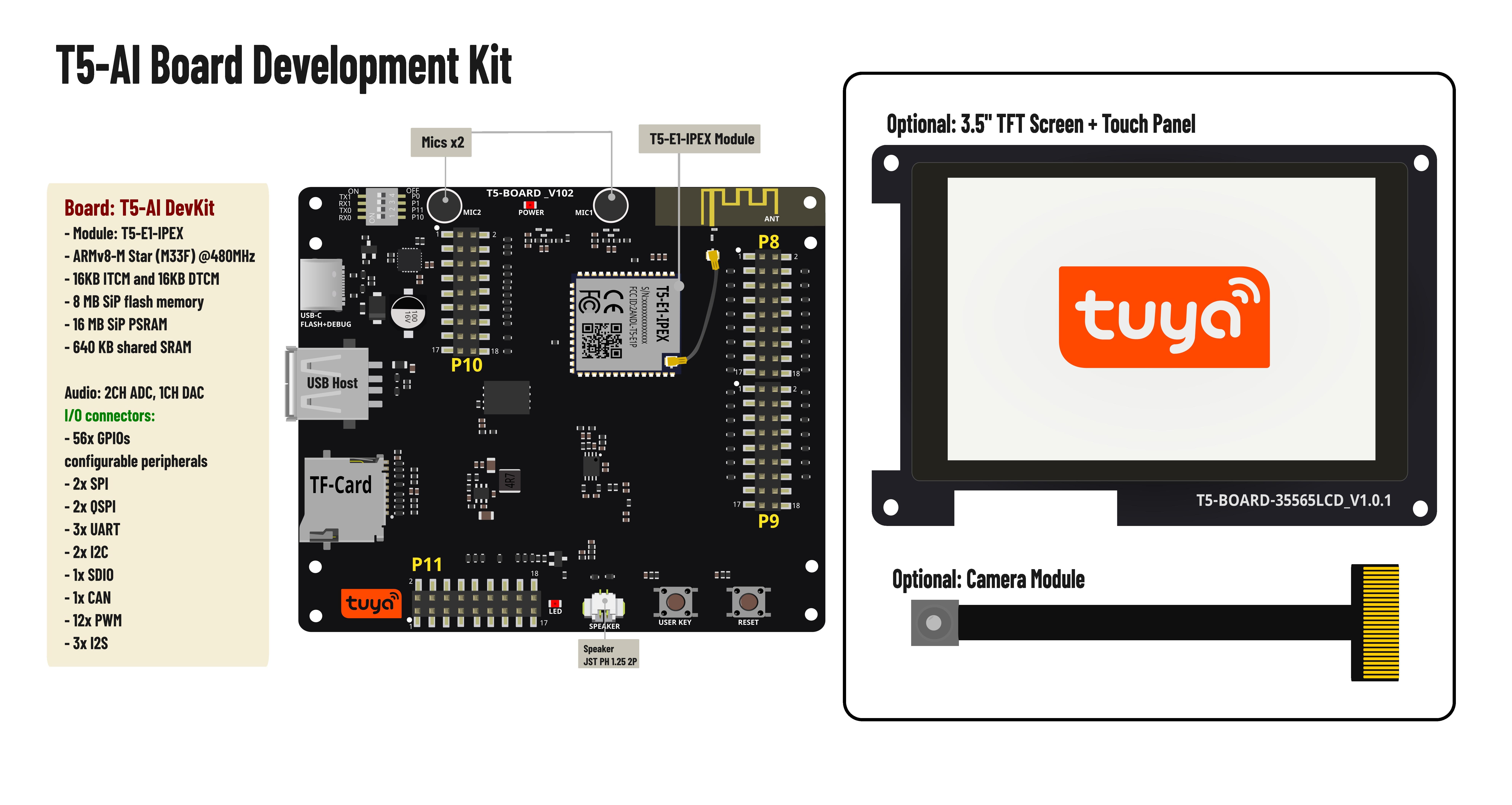
The T5AI-Board is based on the T5-E1-IPEX module, an embedded Wi-Fi and Bluetooth combo module developed by Tuya. The board carries 2 microphones and 1 speaker, supporting voice recognition and playback to enable voice interaction.
Through the I/O connectors on the board, you can stack an LCD display module to add touchscreen and camera capture capabilities. You can also design your own LCD screen using the I2C, SPI, 8080, or RGB interface.
Highlights
- Tuya T5 MCU module (Wi-Fi 2.4 GHz + Bluetooth LE 5.4)
- 8 MB flash memory
- 16 MB RAM
- Serial firmware download and debug logging
- 2-channel microphone
- 1-channel speaker
- TF card slot
- Complete module pin breakout
- Onboard 2.4 GHz Wi-Fi antenna
- USB host interface
- USB power supply
- (Optional stack module) RGB565 display + DVP camera support
Detailed specifications
| Feature | Specification |
|---|---|
| Onboard module | T5-E1-IPEX |
| CPU | ARMv8-M Star (M33F) @480 MHz |
| Cache | 16 KB ITCM and 16 KB DTCM |
| Flash memory | 8 MB SiP flash memory |
| RAM | 16 MB SiP PSRAM |
| SRAM | 640 KB shared SRAM |
| Audio ADC | 2-channel 16-bit 48 KHz |
| Audio DAC | 1-channel 16-bit 48 KHz |
| Equalizer | 4-band digital equalizer |
| Camera | DVP interface |
| Display | RGB and 8080 interfaces |
| Extension | TF card support |
| GPIO | 56 GPIOs |
| Interfaces | 2x SPI, 2x QSPI, 3x UART, 2x I2C, 1x SDIO, 1x CAN, 12x PWM, and 3x I2S |
| Standard | IEEE 802.11b/g/n/ax compliant |
| Bluetooth | Bluetooth LE 5.4 |
| USB type-C | Input: 5V@1A, firmware download and debugging |
Pinout
The T5AI-Board provides comprehensive pinout options through its expansion headers. Here is a detailed breakdown of the available pins and their functionalities.
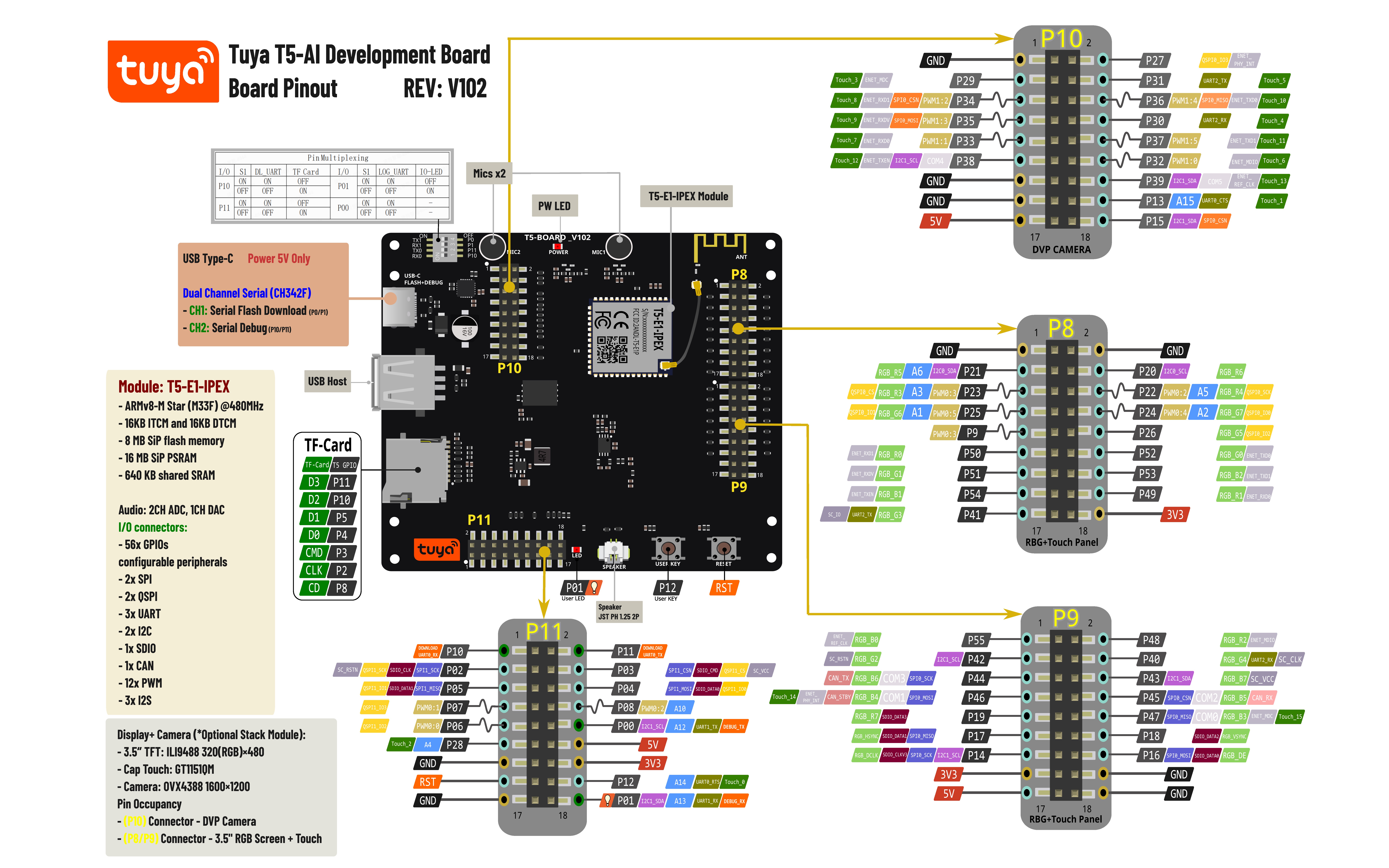
Download high-resolution pinout diagram

LCD and camera module
The T5AI-Board supports an optional LCD and camera module that stacks onto the baseboard.
Display specifications
- 3.5" TFT display with 320 × 480 RGB resolution
- TFT display driver:
ILI9488 - Touch panel driver:
GT1151QM
Camera specifications
- Image sensor:
GC2145 - Resolution: 2 MP (1616 × 1232 pixels)
- I2C communication addresses:
0x78and0x79 - View the camera datasheet
Pin configuration
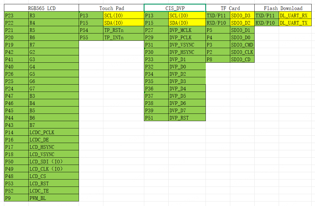
The following diagram shows the pin assignments used by the LCD and camera module:
:::info Important note
- The camera and touch panel share a common I2C interface.
- TF card pins
DATA3andDATA2are shared with the module's UART port for firmware updates. :::
Resources
T5AI-Board development board
- T5AI-Board schematic diagram: Complete circuit diagram.
- T5AI-Board pinout: Detailed pin mapping and interface layout.
- Schematic diagram of LCD and camera module: Circuit diagrams of the LCD and camera module boards.
- T5AI-Board 3D structural file (LCD+Base-Board)(STEP): Offers a 3D model for structural design and integration.
T5 MCU datasheets
- T5-E1-IPEX Module Datasheet: Technical specifications and pin definitions of the T5-E1-IPEX module.
- T5 MCU Chip Technical Datasheet: Comprehensive technical specifications and reference documentation for the T5 series.
USB-to-serial chip driver installation
T5AI-Board uses an onboard CH343 USB-to-serial chip for firmware flashing and debugging. Download the appropriate driver for your operating system: