T5AI-Core Development Kit
The T5AI-Core is a compact voice-core development board built on the Tuya T5-E1 Wi-Fi and Bluetooth combo module. It integrates an onboard microphone, speaker, lithium-battery power management, and a 44-pin header that breaks out the module's GPIO, UART, SPI, and I2C signals. Use it to prototype portable AIoT voice-interaction applications with the standard TuyaOpen workflow.
Software build configuration
The board-level configuration file defines key functional components, such as peripheral drivers, pin mapping, board support packages (BSP), and third-party libraries. By using the pre-configured board-level configuration files for the development board, you can significantly reduce the workload of hardware adaptation and driver development, thus improving development efficiency.
:::tip Interested in developing new peripherals? Configuration features:
- To add a new peripheral, you can write drivers directly at the application layer. BSP drivers are primarily intended for peripherals integrated on the board.
- Peripheral requirements might vary across applications. You must adjust the configuration files based on specific needs.
- Depending on your application requirements, you might need to configure different third-party library parameters.
- It is recommended to make board-level configurations on top of the provided initial configuration file, and perform custom development and functional extensions. :::
How to enable board-level configurations? Refer to CLI - tos.py Development Tool > config choice.
| Build flag | TUYA_T5AI_CORE.config | T5AI-Core + Onboard mic/speaker BSP board configuration - Configuration file |
|---|---|---|
| BSP driver source code | T5AI-Core BSP driver source code | |
Hardware overview
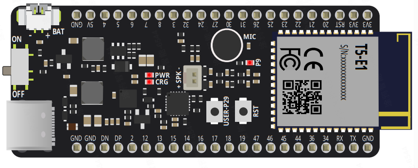
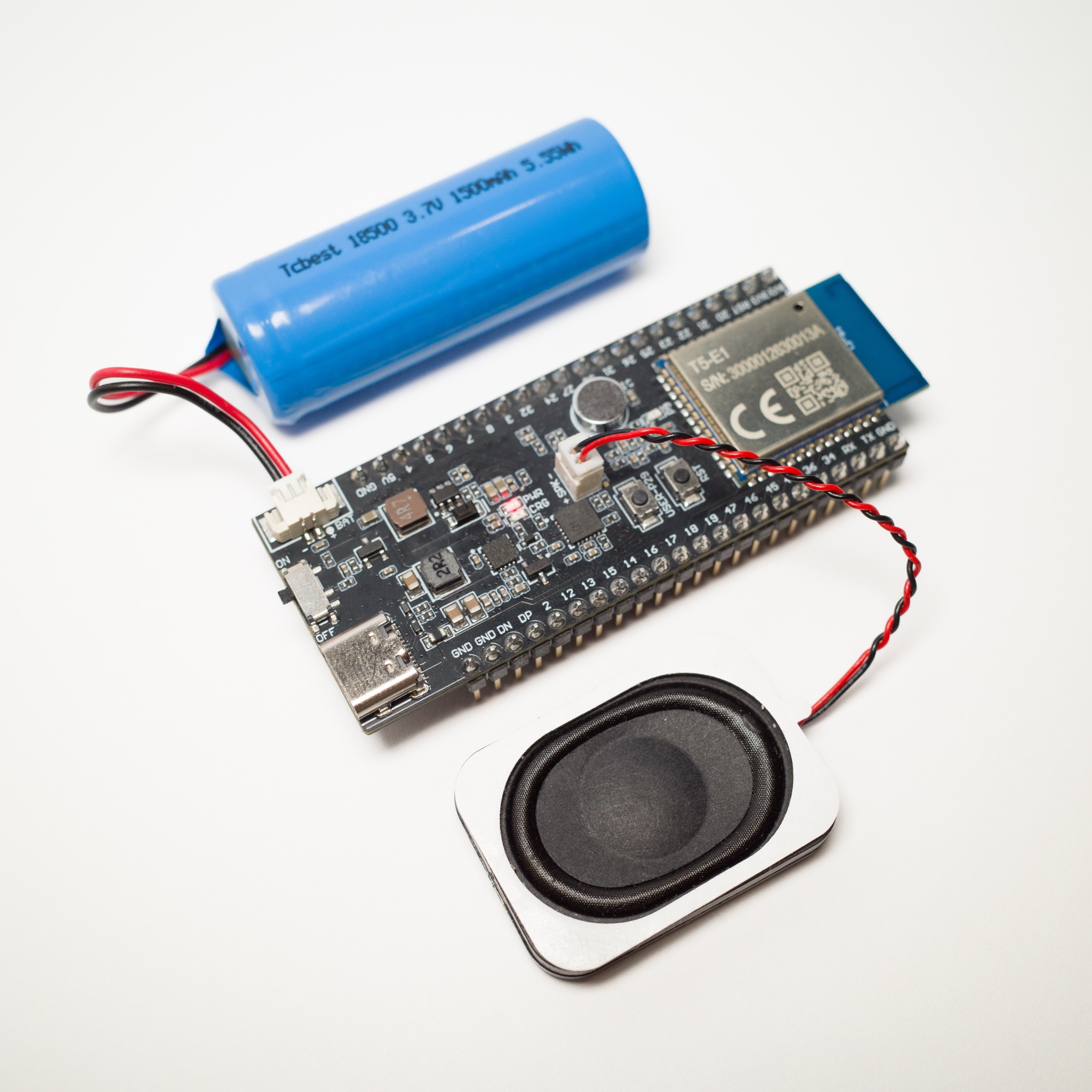
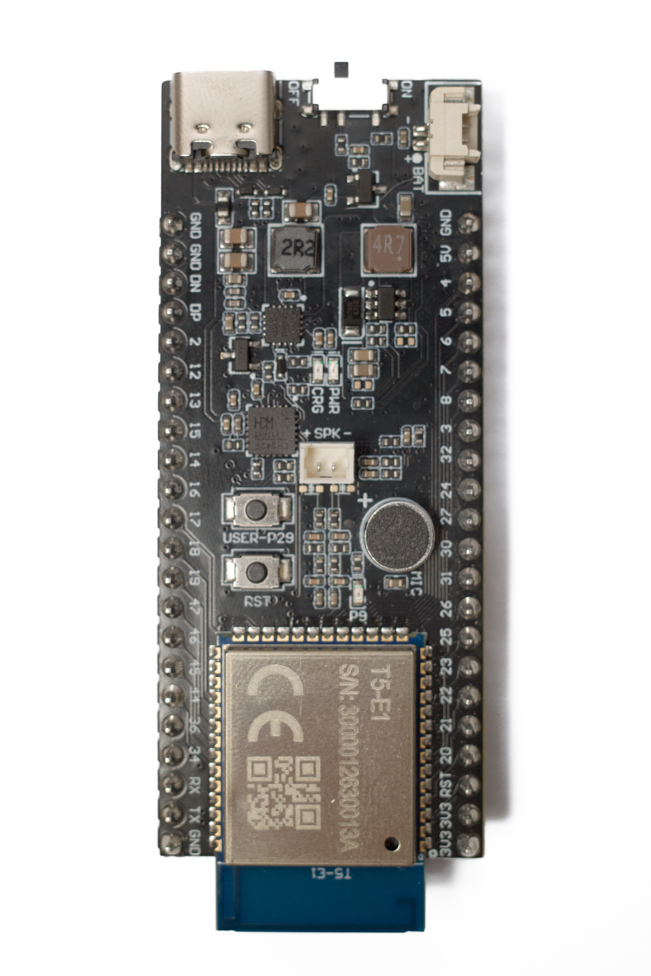
The T5AI-Core is a highly integrated voice-core development board based on the T5-E1 module. The T5-E1 module, independently developed by Tuya, incorporates embedded Wi-Fi and Bluetooth, making it suitable for a variety of smart hardware scenarios. The board features an onboard microphone and speaker, supporting local voice recognition and audio playback to meet voice-interaction requirements.
The board includes a 44-pin header so you can quickly develop and prototype AIoT projects. An onboard lithium-battery power management circuit supports low-power design, suitable for mobile and portable smart devices.
With extensive hardware interfaces and comprehensive voice functionality, the board is well suited to AIoT voice-interaction development.
Highlights
- Tuya T5 MCU module (Wi-Fi 2.4 GHz + Bluetooth LE 5.4)
- ARMv8-M Star (M33F) processor, up to 480 MHz
- 8 MB flash memory (internal to the module chip)
- 16 MB RAM (internal to the module chip)
- Serial firmware download and debug logging
- 1-channel microphone
- 1-channel echo sampling
- 1-channel speaker
- Module pin breakout
- Onboard 2.4 GHz Wi-Fi antenna
- USB power supply + dual serial port chip
- Board dimensions: 73 mm × 29 mm × 11 mm (excluding pin headers) / 17 mm (including pin headers)
Hardware architecture
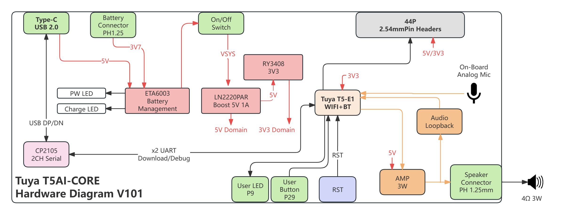
Design philosophy and pin availability
This board was designed with a focus on both portability and development flexibility. It integrates only core functional modules such as battery power supply, firmware flashing and debugging, and audio input/output. Therefore, the board is ready to use out of the box and can satisfy the main application scenarios like voice interaction.
In addition to the core functionalities mentioned above, all other pins are fully accessible through the 44-pin header, significantly enhancing hardware extensibility and accessibility. You can flexibly connect various external sensors, actuators, or other peripherals based on actual project requirements, greatly facilitating prototyping and functional validation. This design not only achieves a concise and efficient board layout but also provides a solid hardware foundation for future feature extension and custom development.
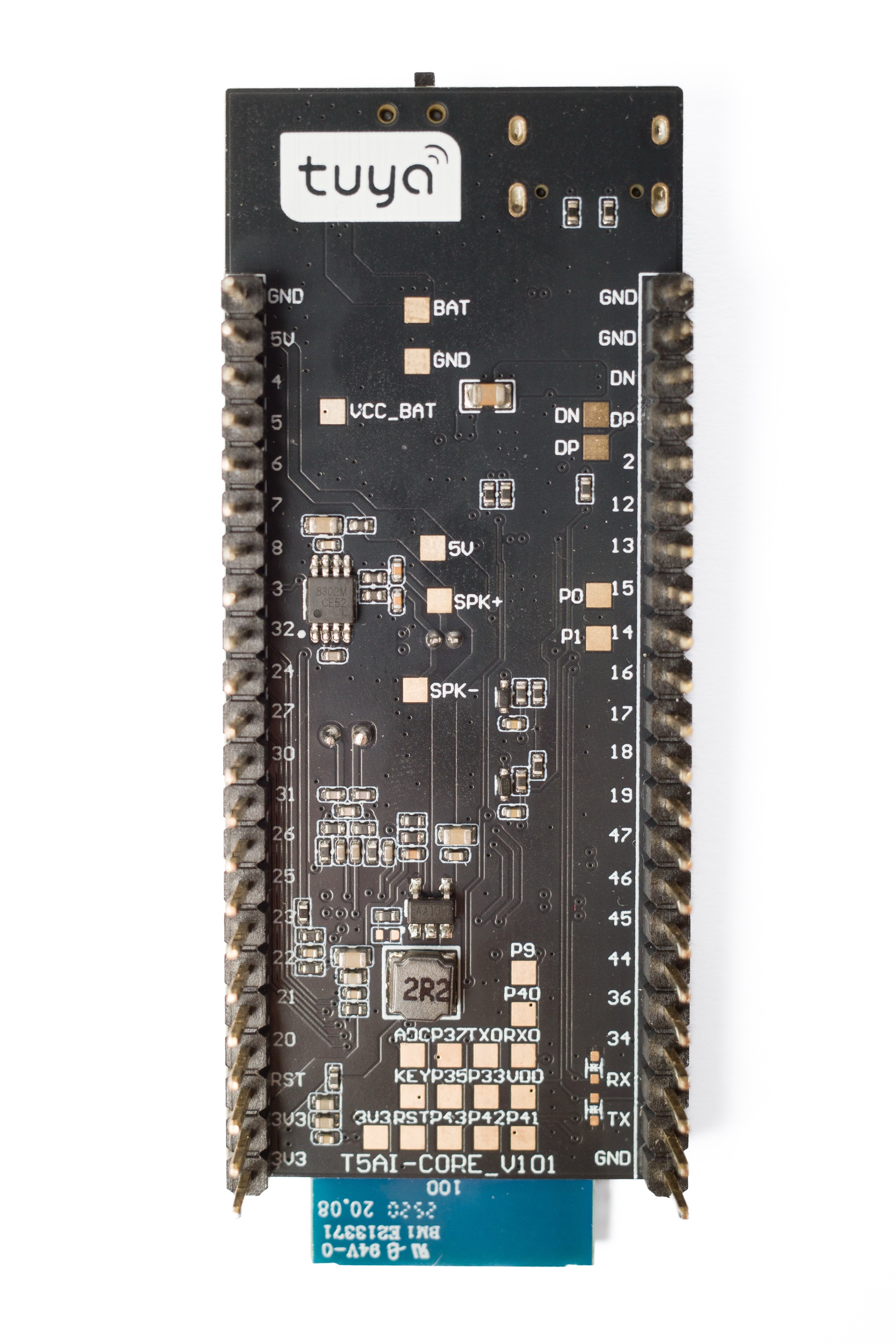
To accommodate additional I/O interfaces, pad test points are reserved on the PCB surface, offering comprehensive extensibility while maintaining a compact form factor.
Hardware details
Power management system
Power input
-
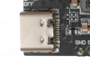
Type-C USB 2.0 port: Provides 5V main power input, and supports firmware flashing and log debugging via dual-channel serial ports.
-
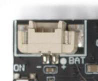
JST PH 1.25 mm battery connector: Supports 3.7V lithium battery power supply for portable applications.
Power switch
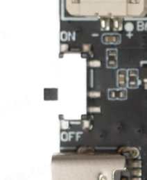
A toggle switch serves as the main power switch of the system, with its upstream power supplied from either USB port or a lithium battery.
Make sure the power switch is turned on when flashing the firmware.
Power management chip
ETA6003 battery management chip:
- Accepts 5V input from the Type-C USB port and 3.7V input from the battery connector.
- Manages battery charging and power distribution.
- Outputs 5V to the power switch.
- Controls the power indicator (PW LED) and charging indicator (Charge LED).
Power switch and regulation
- Power switch: Controls the main system voltage (
VSYS) and receives 5V input from the ETA6003 chip. - LN2220PAR boost converter: Steps up
VSYSto a stable 5V power domain to supply high-power components such as the audio amplifier. - RY3408 3.3V regulator: Steps down the boosted 5V to a 3.3V power domain to supply the T5-E1 module and digital circuits.
Power supply features
- Dual power input: 5V from the USB port and 3.7V from the lithium battery.
- Smart power management supporting battery charging and power switching.
- Multi-stage voltage regulation, providing stable 5V and 3.3V power domains.
- Low-power design optimized for portable applications.
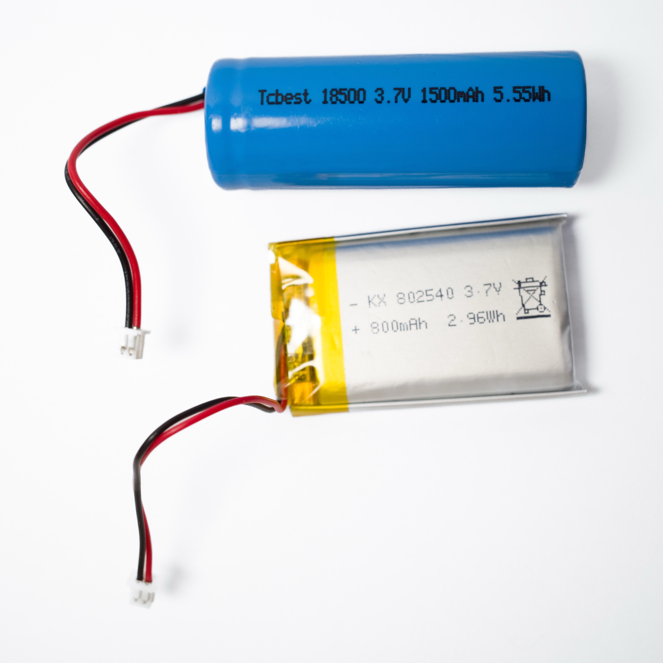
:::warning Battery requirements
- Battery type: 3.7V lithium batteries with a discharge rate of at least 1C are recommended to ensure a stable system power supply.
- Capacity recommendation: Select an appropriate capacity based on application needs, typically ranging from 500 mAh to 2000 mAh.
- Polarity consideration: Strictly follow the positive and negative markings when connecting the battery to avoid reverse connection and device damage.
- Protection circuit: It is advised to use lithium batteries with overcharge, over-discharge, and short-circuit protection features to enhance safety.
:::
Charge LED
ETA6003 battery management chip controls the charge LED to show the current charging status. The logic is as follows:
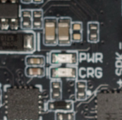
- When the toggle switch is in the On position, the power LED lights up, indicating the system is powered on.
- Charging: When the lithium battery is charging, the charge LED is steady on, indicating charging is in progress.
- Fully charged: When the lithium battery is fully charged, the charge LED automatically turns off, indicating charging is completed.
- No battery or not charging: The charge LED blinks continuously.
To check the charging status, observe whether the charge LED on the development board is lit.
Core processing unit
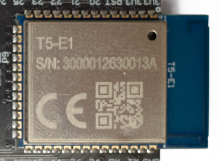
T5-E1 Wi-Fi and Bluetooth module
- Processor: ARMv8-M Star (M33F) architecture, with a maximum clock rate of 480 MHz.
- Storage: Built-in 8 MB flash memory and 16 MB RAM.
- Wireless communication: Integrated 2.4 GHz Wi-Fi and Bluetooth low energy (LE) 5.4 functionality.
- Power supply: Operates within the 3.3V power domain.
- Feature: Acts as the core processing unit, handling all computation, communication, and control tasks.
Communication interfaces
USB serial communication
-
CP2105 dual-channel serial chip:
- Connects to the DP/DN signal lines of the Type-C USB interface.
- Provides dual UART download and debugging functionality.
- Supports firmware flashing and debugging log output.
-
Driver installation: Refer to the USB-to-serial driver installation.
User interaction components
User input and output
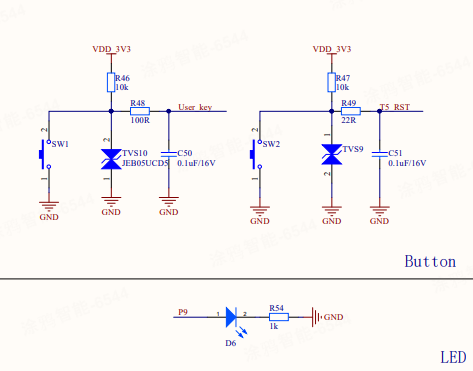
| Component | Pin | Description |
|---|---|---|
| User LED | P9 | User indicator light controlled by the T5-E1 module, connected to GPIO pin P9. |
| User button | P29 | User input button, connected to the T5-E1 module's GPIO pin P29. |
| Reset button | RST | Dedicated reset button that sends a reset signal to the T5-E1 module. |

Audio system
Audio sampling specifications
- Standard sampling rate: 16 KHz
- Sampling bit depth: 16 bits
The T5AI-Core audio system adopts a default sampling rate of 16 KHz and 16-bit sampling precision, making it suitable for applications such as voice recognition and audio processing. It is compatible with popular audio algorithms and protocols.
Audio input
The T5 module supports two channels of analog microphone input, facilitating audio capture and loopback. The audio input channels on this board are assigned as follows:
| Channel | Purpose description |
|---|---|
| CH1 | Microphone audio input |
| CH2 | Speaker loopback signal input (supports interrupt functionality) |
- Onboard analog microphone: An integrated microphone that provides analog audio input to the T5-E1 module.
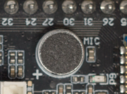
- Loopback circuit: An audio loopback circuit designed for audio testing and processing. It supports Acoustic Echo Cancellation (AEC) and echo suppression features, and is connected to the T5-E1 module.
Audio output
- 1W audio amplifier:
- Powered by the 5V power domain.
- Receives audio signals from the T5-E1 module.
- Outputs amplified audio to the speaker connector.
- JST PH 1.25 mm speaker connector: External speaker output interface, compatible with 4Ω 3W speakers.
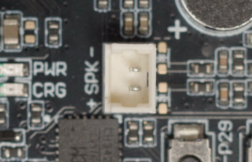
:::warning Speaker selection It is recommended to use speakers with 4Ω impedance and 1W to 3W power. Make sure your selected speakers have good echo cancellation and noise suppression performance to meet the audio system requirements. :::
Extension interfaces
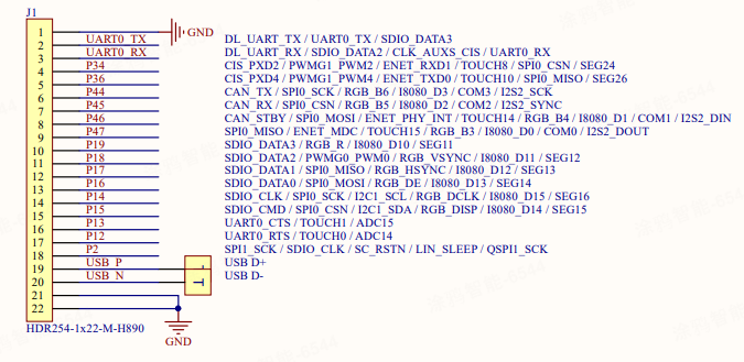
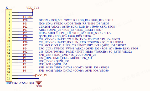
44-pin 2.54 mm header
- Power pins: Provide 5V and 3.3V power outputs.
- Signal pins: Expose various signals from the T5-E1 module, including GPIO, UART, SPI, and I2C.
- Functionality: Facilitate external circuit connections and functional extension, supporting rapid prototype verification.
The following section details pin multiplexing and functional definitions:
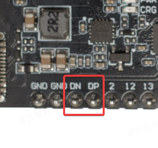
USB host interface (Functional extension)
The T5 module supports one USB host channel, enabling connections to various USB devices, such as USB cameras and USB serial ports using the Communications Device Class (CDC). Thus, the module can meet diverse peripheral extension requirements.
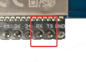
Firmware download UART (Multiplexed)
The UART pins of the T5 module are shared with the onboard serial chip. After firmware flashing is completed, the UART port can be reassigned for other device applications, enabling flexible management of serial resources.
Antenna system
Onboard 2.4 GHz Wi-Fi and Bluetooth LE antenna: An integrated antenna that provides wireless communication support for the T5-E1 module.
Resources
T5AI-Core development board
- T5AI-Core schematic diagram: Complete circuit diagram.
- T5AI-Core silkscreen (ASM): Provides detailed silkscreen reference for this board.
- T5AI-Core 3D structural file (STEP): Offers a 3D model for structural design and integration.
T5 MCU datasheets
- T5-E1 Module Datasheet: Technical specifications and pin definitions of the T5-E1 module.
- T5 MCU Chip Technical Datasheet: Comprehensive technical specifications and reference documentation for the T5 series.
USB-to-serial chip driver installation
The T5AI-Core uses an onboard CH343 USB-to-serial chip for firmware flashing and debugging. Download the appropriate driver for your operating system: