Build AI Chatbot with T5AI-Core
Overview
This article introduces how to quickly build an AI chatbot using T5AI-Core. First, please refer to T5AI-Core Development Kit to understand the detailed information about T5AI-Core.
The pin connection definitions between T5AI-Core and ST7789 screen are as follows (same as EVB):
| T5AI-Core | ST7789 Screen |
|---|---|
| P14 | SPI0_SCK |
| P16 | SPI0_MOSI |
| P6 | LCD_RES |
| P17 | LCD_DC |
| P15 | LCD_CSN |
| P5 | LCD_BL_ON |
| P7 | LCD_PWR_ON |
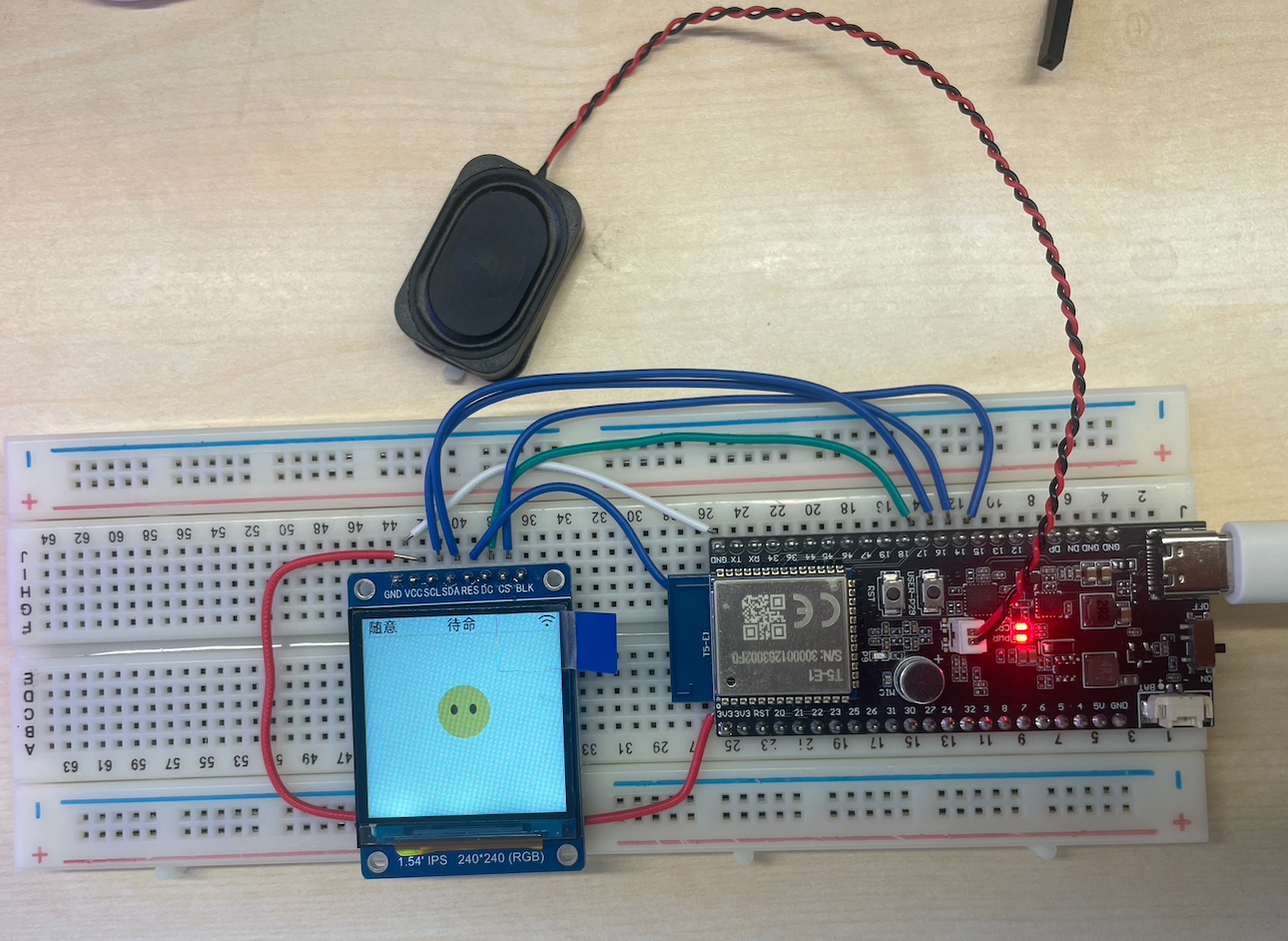
Effect Image:
Configure menuconfig
-
First, please refer to Download and Activate TuyaOpen to activate
tos.py. -
Enter
cd apps/tuya.ai/your_chat_bot && tos.py config menuin the terminal and run it, then modify the configuration information in the code according to your actual needs as shown in the figure below.- Modify PID, select chat interface UI:
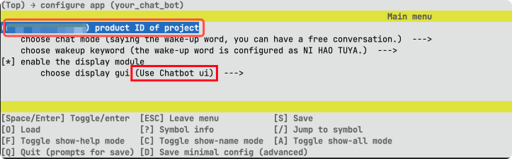
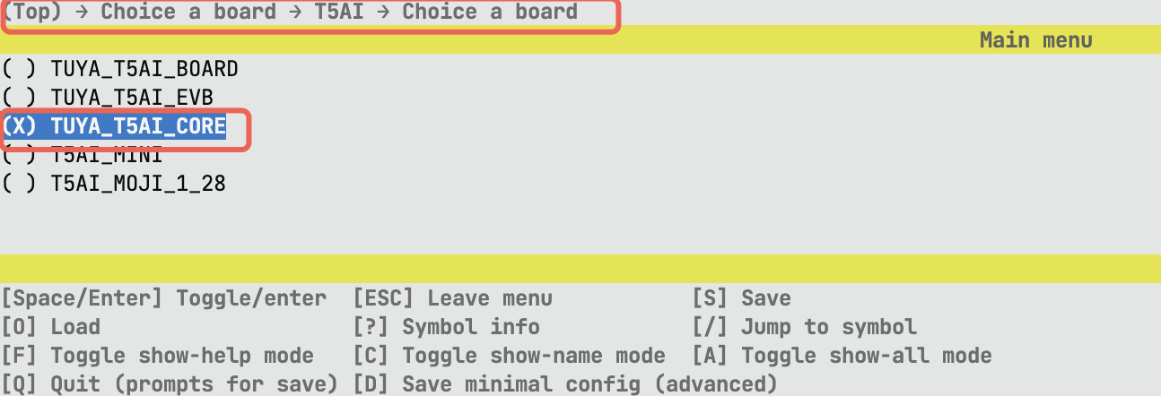
Modify PID.png - Select development board:
Select Development Board.png - Enable color inversion:
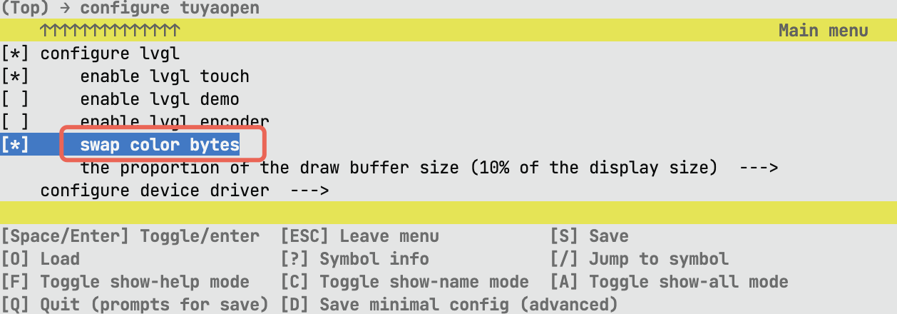
Enable Color Inversion.png
- Modify PID, select chat interface UI:
Code Modification
Add T5AI-Core Definition in Screen Font Initialization Interface
-
Find the
get_ui_fontinterface in theapps/tuya.ai/your_chat_bot/src/display/app_display.cfile. -
At the position shown in the figure below, add the
|| BOARD_CHOICE_TUYA_T5AI_COREcode.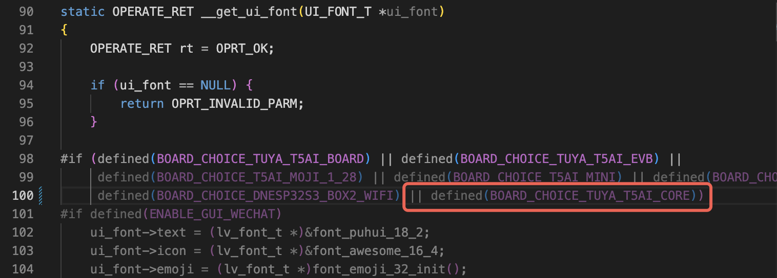
Add T5AI-Core Definition.png
Fill in Authorization Code
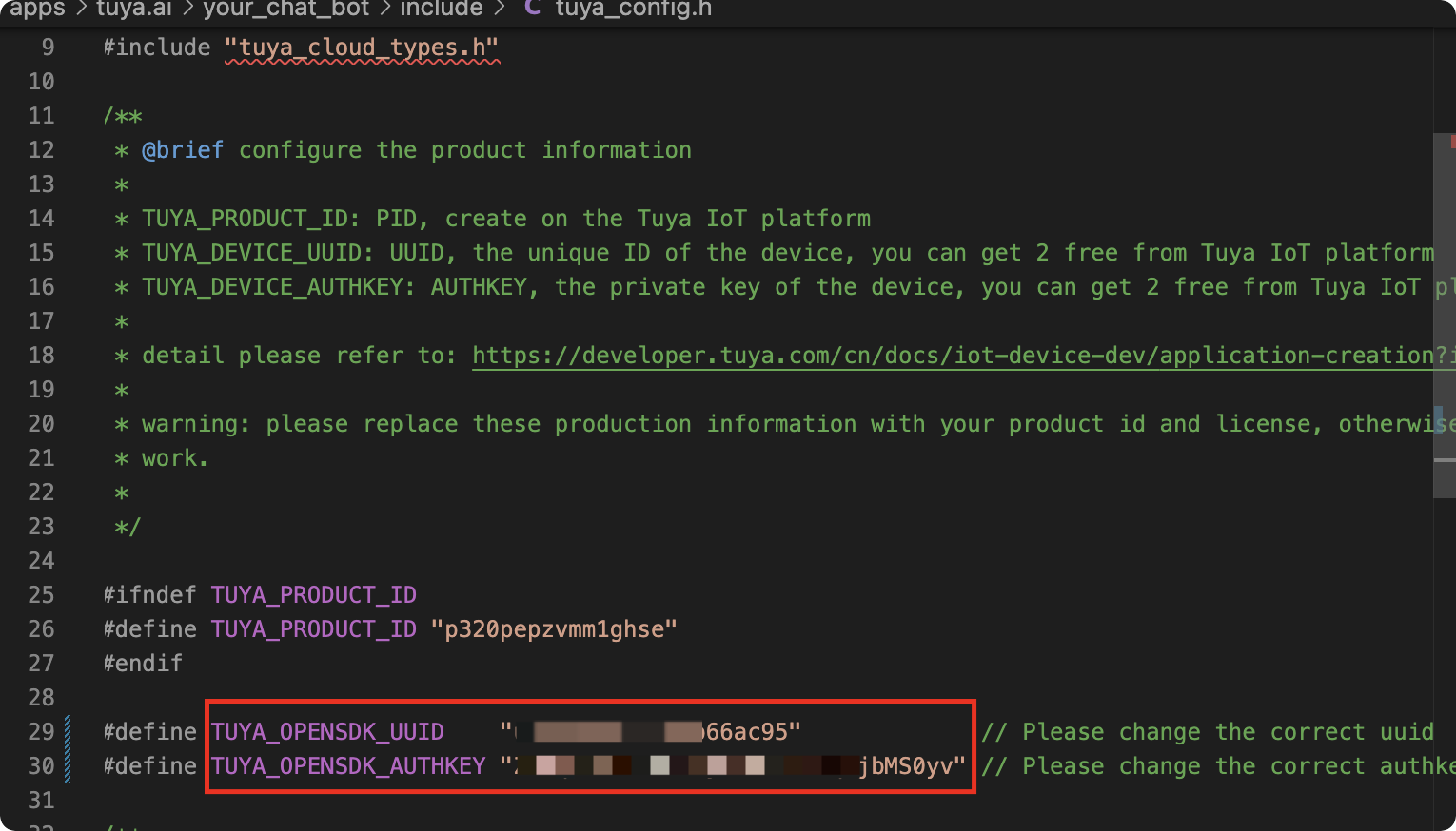
Find the apps/tuya.ai/your_chat_bot/include/tuya_config.h file, and fill in the authorization codes (UUID and Authkey) into the TUYA_OPENSDK_UUID and TUYA_OPENSDK_AUTHKEY macro definitions respectively, as shown in the figure below:
Add Display Driver
Add display driver code in the TuyaOpen/boards/T5AI/TUYA_T5AI_CORE/tuya_t5ai_core.c file. You can copy the code below and completely replace your original code.
/**
 * @file tuya_t5ai_core.c
 * @brief tuya_t5ai_core module is used to
 * @version 0.1
 * @copyright Copyright (c) 2021-2025 Tuya Inc. All Rights Reserved.
 */

#include "tuya_cloud_types.h"

#include "tal_api.h"

#include "tdd_audio.h"
#include "tdd_led_gpio.h"
#include "tdd_button_gpio.h"
#include "tdd_disp_st7789.h"
/***********************************************************
************************macro define************************
***********************************************************/
#define BOARD_SPEAKER_EN_PIN TUYA_GPIO_NUM_39

#define BOARD_BUTTON_PIN       TUYA_GPIO_NUM_29
#define BOARD_BUTTON_ACTIVE_LV TUYA_GPIO_LEVEL_LOW

#define BOARD_LED_PIN       TUYA_GPIO_NUM_9
#define BOARD_LED_ACTIVE_LV TUYA_GPIO_LEVEL_HIGH

#define BOARD_LCD_BL_TYPE            TUYA_DISP_BL_TP_GPIO
#define BOARD_LCD_BL_PIN             TUYA_GPIO_NUM_5
#define BOARD_LCD_BL_ACTIVE_LV       TUYA_GPIO_LEVEL_HIGH

#define BOARD_LCD_WIDTH              240
#define BOARD_LCD_HEIGHT             240
#define BOARD_LCD_PIXELS_FMT         TUYA_PIXEL_FMT_RGB565
#define BOARD_LCD_ROTATION           TUYA_DISPLAY_ROTATION_0

#define BOARD_LCD_SPI_PORT           TUYA_SPI_NUM_0
#define BOARD_LCD_SPI_CLK            48000000
#define BOARD_LCD_SPI_CS_PIN         TUYA_GPIO_NUM_15
#define BOARD_LCD_SPI_DC_PIN         TUYA_GPIO_NUM_17
#define BOARD_LCD_SPI_RST_PIN        TUYA_GPIO_NUM_6

#define BOARD_LCD_PIXELS_FMT         TUYA_PIXEL_FMT_RGB565

#define BOARD_LCD_POWER_PIN          TUYA_GPIO_NUM_7
#define BOARD_LCD_POWER_ACTIVE_LV    TUYA_GPIO_LEVEL_HIGH

/***********************************************************
***********************typedef define***********************
***********************************************************/

/***********************************************************
********************function declaration********************
***********************************************************/

/***********************************************************
***********************variable define**********************
***********************************************************/

/***********************************************************
***********************function define**********************
***********************************************************/
OPERATE_RET __board_register_audio(void)
{
    OPERATE_RET rt = OPRT_OK;

#if defined(AUDIO_CODEC_NAME)
    TDD_AUDIO_T5AI_T cfg = {0};
    memset(&cfg, 0, sizeof(TDD_AUDIO_T5AI_T));

    cfg.aec_enable = 1;

    cfg.ai_chn = TKL_AI_0;
    cfg.sample_rate = TKL_AUDIO_SAMPLE_16K;
    cfg.data_bits = TKL_AUDIO_DATABITS_16;
    cfg.channel = TKL_AUDIO_CHANNEL_MONO;

    cfg.spk_sample_rate = TKL_AUDIO_SAMPLE_16K;
    cfg.spk_pin = BOARD_SPEAKER_EN_PIN;
    cfg.spk_pin_polarity = TUYA_GPIO_LEVEL_LOW;

    TUYA_CALL_ERR_RETURN(tdd_audio_register(AUDIO_CODEC_NAME, cfg));
#endif
    return rt;
}

static OPERATE_RET __board_register_button(void)
{
    OPERATE_RET rt = OPRT_OK;

#if defined(BUTTON_NAME)
    BUTTON_GPIO_CFG_T button_hw_cfg = {
        .pin = BOARD_BUTTON_PIN,
        .level = BOARD_BUTTON_ACTIVE_LV,
        .mode = BUTTON_TIMER_SCAN_MODE,
        .pin_type.gpio_pull = TUYA_GPIO_PULLUP,
    };

    TUYA_CALL_ERR_RETURN(tdd_gpio_button_register(BUTTON_NAME, &button_hw_cfg));
#endif

    return rt;
}

static OPERATE_RET __board_register_led(void)
{
    OPERATE_RET rt = OPRT_OK;

#if defined(LED_NAME)
    TDD_LED_GPIO_CFG_T led_gpio;

    led_gpio.pin = BOARD_LED_PIN;
    led_gpio.level = BOARD_LED_ACTIVE_LV;
    led_gpio.mode = TUYA_GPIO_PUSH_PULL;

    TUYA_CALL_ERR_RETURN(tdd_led_gpio_register(LED_NAME, &led_gpio));
#endif

    return rt;
}

static OPERATE_RET __board_register_display(void)
{
    OPERATE_RET rt = OPRT_OK;

#if defined(DISPLAY_NAME)
    DISP_SPI_DEVICE_CFG_T display_cfg;

    memset(&display_cfg, 0, sizeof(DISP_RGB_DEVICE_CFG_T));

    display_cfg.bl.type              = BOARD_LCD_BL_TYPE;
    display_cfg.bl.gpio.pin          = BOARD_LCD_BL_PIN;
    display_cfg.bl.gpio.active_level = BOARD_LCD_BL_ACTIVE_LV;

    display_cfg.width     = BOARD_LCD_WIDTH;
    display_cfg.height    = BOARD_LCD_HEIGHT;
    display_cfg.pixel_fmt = BOARD_LCD_PIXELS_FMT;
    display_cfg.rotation  = BOARD_LCD_ROTATION;

    display_cfg.port      = BOARD_LCD_SPI_PORT;
    display_cfg.spi_clk   = BOARD_LCD_SPI_CLK;
    display_cfg.cs_pin    = BOARD_LCD_SPI_CS_PIN;
    display_cfg.dc_pin    = BOARD_LCD_SPI_DC_PIN;
    display_cfg.rst_pin   = BOARD_LCD_SPI_RST_PIN;

    display_cfg.power.pin          = BOARD_LCD_POWER_PIN;
    display_cfg.power.active_level = BOARD_LCD_POWER_ACTIVE_LV;

    TUYA_CALL_ERR_RETURN(tdd_disp_spi_st7789_register(DISPLAY_NAME, &display_cfg));
#endif

    return rt;
}

/**
 * @brief Registers all the hardware peripherals (audio, button, LED) on the board.
 *
 * @return Returns OPERATE_RET_OK on success, or an appropriate error code on failure.
 */
OPERATE_RET board_register_hardware(void)
{
    OPERATE_RET rt = OPRT_OK;

    TUYA_CALL_ERR_LOG(__board_register_audio());

    TUYA_CALL_ERR_LOG(__board_register_button());

    TUYA_CALL_ERR_LOG(__board_register_led());
    TUYA_CALL_ERR_LOG(__board_register_display());

    return rt;
}
Compile and Flash
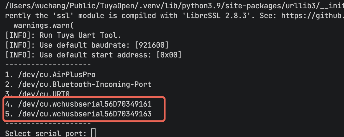
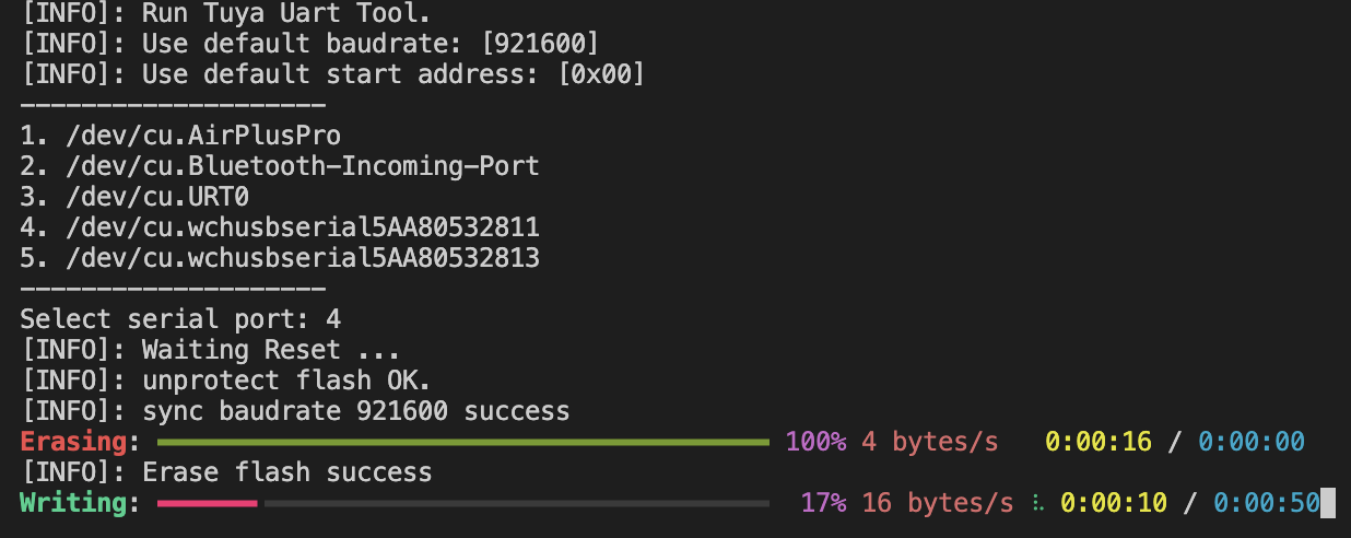
Enter tos.py build && tos.py flash in the terminal and run it.
The development board has two serial ports, one for flashing firmware and one for log printing. Please try and select as needed, as shown in the figure below:
After flashing and running, the normal running result is shown in the figure below:
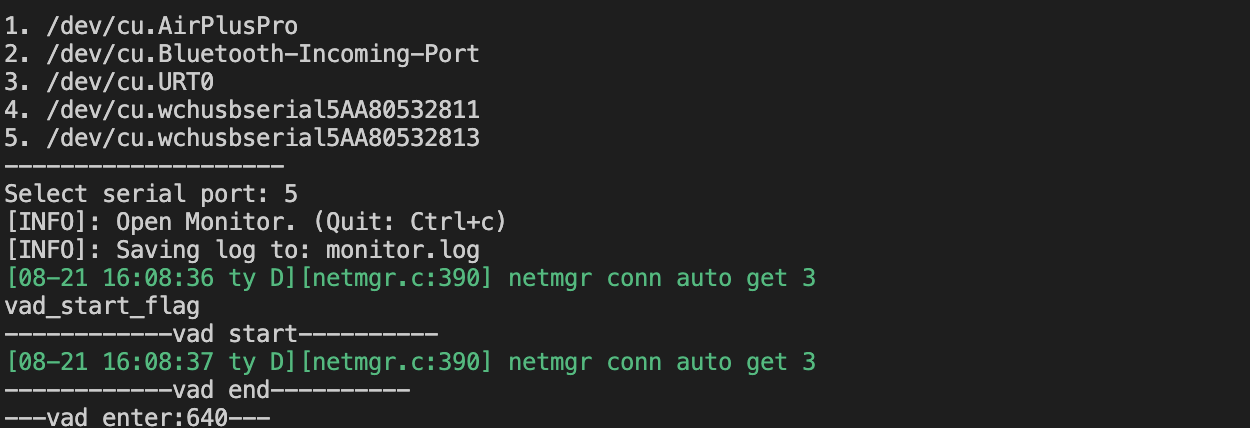
Log Monitoring
Enter tos.py monitor in the terminal and run it, as shown in the figure below: