tlk_i2s | I2S Driver
Brief Description
I2S, short for Inter-IC Sound or Integrated Interchip Sound, is a digital audio transmission standard defined by Philips in 1986 (revised in 1996). It is used for the transmission of digital audio data between internal components within a system, such as codecs, DSPs, digital input/output interfaces, ADCs, DACs, and digital filters.
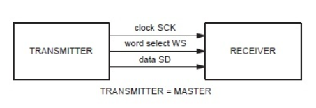
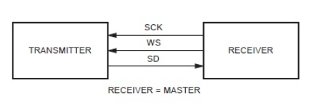
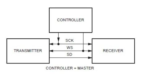
I2S is a relatively simple digital interface protocol without an address or device selection mechanism. On the I2S bus, there can only be one master device and one transmitter device at the same time. The master device can be the transmitter, the receiver, or another control device that coordinates the transmitter and receiver.
In an I2S system, the device that provides the clock (SCK and WS) is the master device. Below are some common I2S system block diagrams.


Where:
SCK: There is a pulse for every bit of digital audio, with the SCK frequency equal to 2 × sample rate × sample bit depth.
WS: Used to switch data between the left and right channels. The WS frequency equals the sample rate, with WS at "1" indicating that left channel data is being transmitted, and WS at "0" indicating that right channel data is being transmitted.
SD: Serial data, represented by binary补码 audio data.
API Description
tkl_i2s_init
OPERATE_RET tkl_i2s_init(TUYA_I2S_NUM_E i2s_num, const TUYA_I2S_BASE_CFG_T *i2s_config);
-
Function Description:
- Initializes the corresponding I2S instance via the device number and base configuration, returning the initialization result.
-
Parameters:
-
i2s_num: Port number. -
i2s_config: Base configurationtypedef struct { TUYA_I2S_MODE_E mode; /*!< I2S work mode */ uint32_t sample_rate; /*!< I2S sample rate */ uint32_t mclk; /*!< I2S mclk */ TUYA_I2S_BITS_PER_SAMP_E bits_per_sample; /*!< I2S sample bits in one channel */ TUYA_I2S_CHANNEL_FMT_E channel_format; /*!< I2S channel format. */ TUYA_I2S_COMM_FORMAT_E communication_format; /*!< I2S communication format */ uint32_t i2s_dma_flags; /*!< I2S dma format , 1 use dma */ } TUYA_I2S_BASE_CFG_T;TUYA_I2S_MODE_E:
Name Definition Remarks TUYA_I2S_MODE_MASTER Master Mode TUYA_I2S_MODE_SLAVE Slave Mode TUYA_I2S_MODE_TX Transmit Mode TUYA_I2S_MODE_RX Receive Mode Users can use four combinations of modes, which are:
- TUYA_I2S_MODE_MASTER|TUYA_I2S_MODE_TX
- TUYA_I2S_MODE_MASTER|TUYA_I2S_MODE_RX
- TUYA_I2S_MODE_SLAVE|TUYA_I2S_MODE_TX
- TUYA_I2S_MODE_SLAVE|TUYA_I2S_MODE_RX
sample_rate: Sample rate.mclk: Master clock, usually 256 or 384 times the sample rate.TUYA_I2S_BITS_PER_SAMP_E:
Name Definition Remarks TUYA_I2S_BITS_PER_SAMPLE_8BIT 8-bit data width TUYA_I2S_BITS_PER_SAMPLE_16BIT 16-bit data width TUYA_I2S_BITS_PER_SAMPLE_24BIT 24-bit data width TUYA_I2S_BITS_PER_SAMPLE_32BIT 32-bit data width TUYA_I2S_CHANNEL_FMT_E:
Name Definition Remarks TUYA_I2S_CHANNEL_FMT_RIGHT_LEFT Separate left and right channels TUYA_I2S_CHANNEL_FMT_ALL_RIGHT Load right channel data to both channels TUYA_I2S_CHANNEL_FMT_ALL_LEFT Load left channel data to both channels TUYA_I2S_CHANNEL_FMT_ONLY_RIGHT Load only right channel data Mono mode TUYA_I2S_CHANNEL_FMT_ONLY_LEFT Load only left channel data Mono mode TUYA_I2S_COMM_FORMAT_E:
Name Definition Remarks I2S_COMM_FORMAT_STAND_I2S Philips standard, data is transmitted on the second BCK I2S_COMM_FORMAT_STAND_MSB MSB (left-aligned) standard, data is transmitted on the first BCK I2S_COMM_FORMAT_STAND_PCM_SHORT PCM short standard, also known as DSP mode. The synchronization signal (WS) period is one BCK period. I2S_COMM_FORMAT_STAND_PCM_LONG PCM long standard, the synchronization signal (WS) period is channel_bit BCK periods
-
-
Return Value:
- NULL: Initialization failed.
- Others: Instance handle.
tkl_i2s_send
OPERATE_RET tkl_i2s_send(TUYA_I2S_NUM_E i2s_num, void *buff, uint32_t len);
-
Function Description:
- Transmits data to the transmitter via I2S.
-
Parameters:
-
i2s_num: Port number. -
buff: Pointer to the data to be sent. -
len: Length of the data to be sent.
-
-
Return Value:
- OPRT_OK for success, others please refer to the
OS_ADAPTER_I2Ssection in the filetuya_error_code.h.
- OPRT_OK for success, others please refer to the
tkl_i2s_send_stop
OPERATE_RET tkl_i2s_send_stop(TUYA_I2S_NUM_E i2s_num);
-
Function Description:
- Stops transmitting data to the transmitter via I2S.
-
Parameters:
i2s_num: Port number.
-
Return Value:
- OPRT_OK for success, others please refer to the
OS_ADAPTER_I2Ssection in the filetuya_error_code.h.
- OPRT_OK for success, others please refer to the
tkl_i2s_recv
int tkl_i2s_recv(TUYA_I2S_NUM_E i2s_num, void *buff, uint32_t len);
-
Function Description:
- Asynchronously receives data via I2S.
-
Parameters:
-
i2s_num: Port number. -
buff: Pointer to the buffer where the received data will be stored. -
len: Length of the data to be received.
-
-
Return Value:
- OPRT_OK for success, others please refer to the
OS_ADAPTER_I2Ssection in the filetuya_error_code.h.
- OPRT_OK for success, others please refer to the
tkl_i2s_recv_stop
OPERATE_RET tkl_i2s_recv_stop(TUYA_I2S_NUM_E i2s_num);
-
Function Description:
- Stops receiving data via I2S.
-
Parameters:
i2s_num: Port number.
-
Return Value:
- OPRT_OK for success, others please refer to the
OS_ADAPTER_I2Ssection in the filetuya_error_code.h.
- OPRT_OK for success, others please refer to the
tkl_i2s_deinit
OPERATE_RET tkl_i2s_deinit(TUYA_I2S_NUM_E i2s_num);
-
Function Description:
- De-initializes I2S.
-
Parameters:
i2s_num: Port number.
-
Return Value:
- OPRT_OK for success, others please refer to the
OS_ADAPTER_I2Ssection in the filetuya_error_code.h.
- OPRT_OK for success, others please refer to the